
Reactor stud cleaning booth

Inactive Publication Date: 2001-05-29
STP NUCLEAR OPERATING
View PDF14 Cites 8 Cited by
  • Summary
  • Abstract
  • Description
  • Claims
  • Application Information

AI Technical Summary

Benefits of technology

The circulation system of the present invention stores cleaning agent in a sump. A pump is used to pump the cleaning agent from the sump to a spray nozzle where the agent is sprayed over the reactor stud during cleaning. The cleaning agent is then drained from the compartment and passed through a filter to remove contaminants before it is returned to the sump for reuse. Spent cleaning agent can be drained from the sump and disposed of according to appropriate hazardous waste regulations. The cleaning agent circulation system enhances the cleaning of the reactor studs, while the amount of waste generated is minimized by filtering and reusing the cleaning agent.

Problems solved by technology

The size and weight of the reactor studs made cleaning of the studs a cumbersome and time consuming process.
There were several problems with this process for cleaning reactor studs.
The cleaning process was very laborious and consumed a significant amount of manual labor.
In addition, because of the possibility that the reactor studs were somewhat radioactive, personnel could only be exposed to the studs for a short period of time.
Another problem with the traditional reactor stud cleaning process was that it created a large amount of waste such as rags, scrubbing pads, and brushes that had to be treated as radioactive waste.
There were several problems with these machines.
First, the stud had to be positioned in a horizontal plane requiring extra handling of the potentially radioactive stud.
Additionally, the machines used a mechanical cleaning process and did not have capability to utilize solvents and other cleaning agents.
Further, the machines only had the capability of cleaning one reactor stud at a time.
However, in this apparatus, the rotary brushes were replaced with a high pressure spray nozzle that used water and an abrasive to clean the stud.
This apparatus shared many of the same problems including requiring additional handling to put the studs in the horizontal position and being limited to cleaning one reactor stud at a time.
The ability to keep the reactor studs in a vertical position decreases the handling required and therefore the safety risk associated with handling of the potentially radioactive studs.

Method used


Image

  • Reactor stud cleaning booth
  • Reactor stud cleaning booth
  • Reactor stud cleaning booth

Examples


Embodiment Construction

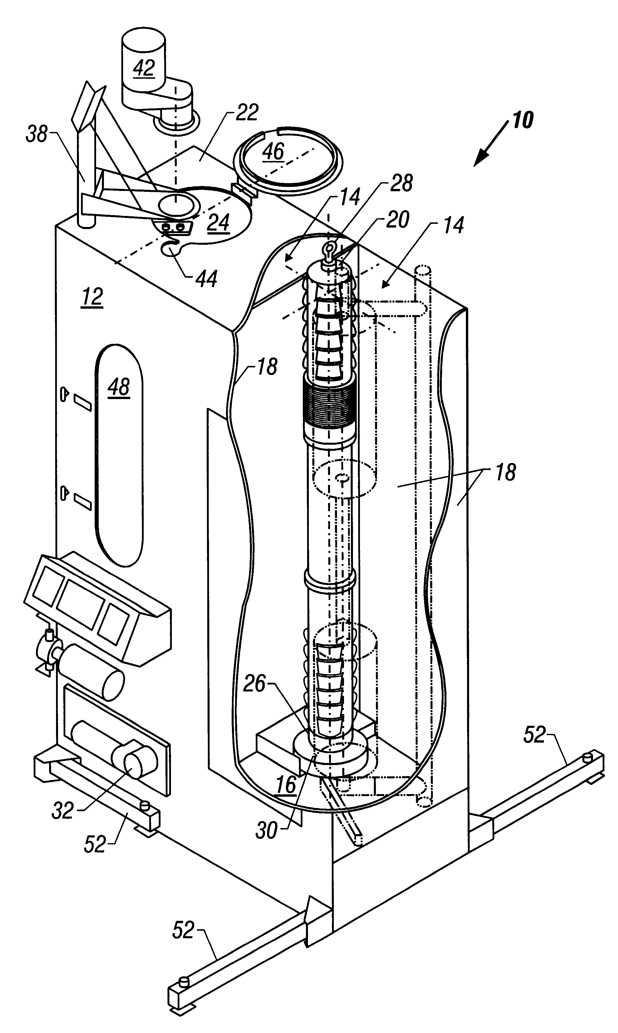
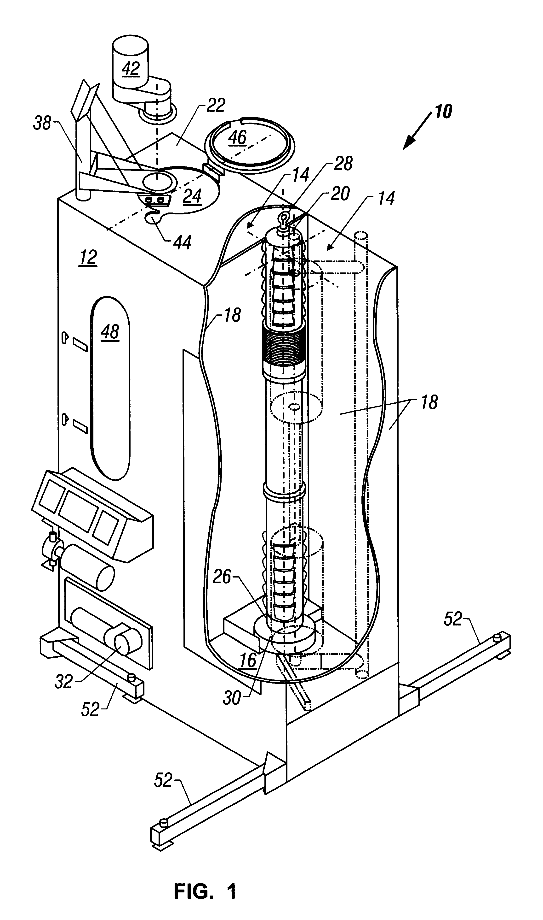
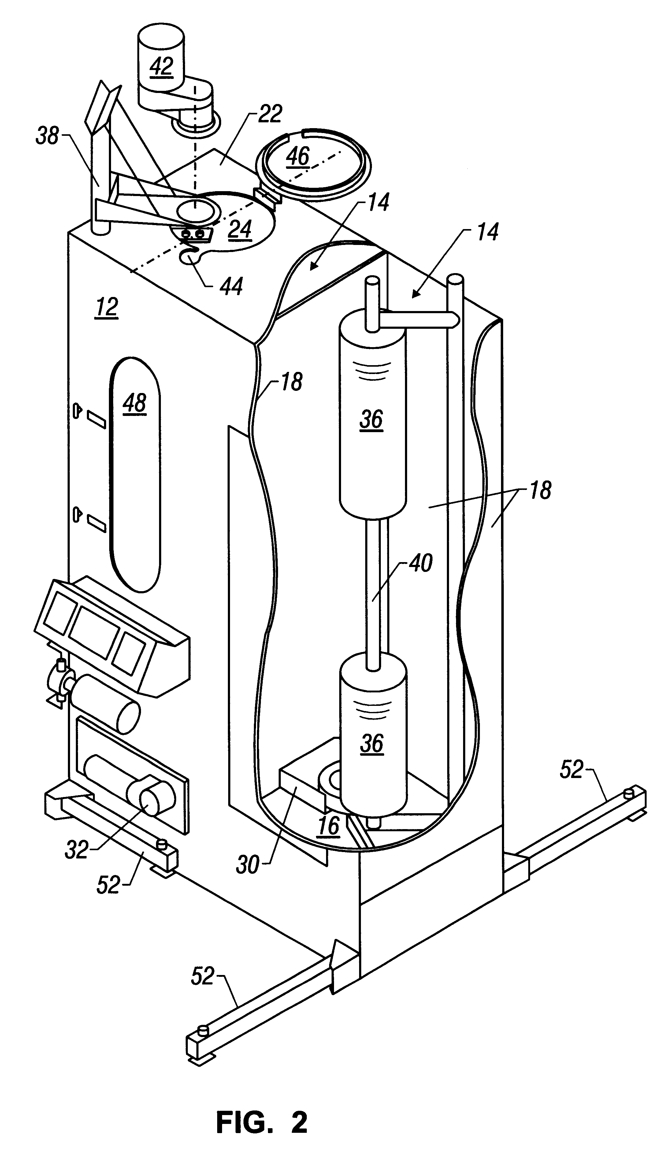
As shown in FIG. 1, the present invention is an apparatus 10 for cleaning large reactor studs 20 which are used to secure reactor heads on nuclear reactors. The present invention overcomes many of the problems of the prior art by providing an apparatus 10 that allows reactor studs 20 to be cleaned in the vertical position. Additionally, the present invention provides for cleaning multiple reactor studs 20 within apparatus 10 thereby increasing the efficiency of the cleaning process. Further, apparatus 10 of the present invention provides for efficient cleaning of reactor studs 20 using both a mechanical cleaning process and cleaning solvents which are recycled and reused.

Apparatus 10 is a self-contained unit having a housing 12 that encloses sealable compartments 14. As shown, the housing 12 encloses two or more sealable compartments 14 each of which is capable of enclosing a reactor stud 20 for cleaning. However, the apparatus of the present invention can be constructed to have mul...


PUM


Abstract

A reactor stud cleaning apparatus is presented for cleaning studs, nuts, and washers used to secure reactor heads on nuclear reactors. The cleaning apparatus is a self-contained unit having a housing that includes two independent sealable compartments allowing cleaning of two studs simultaneously. Each sealable compartment has a topside covering with a port that allows reactor studs to be lowered into the apparatus keeping the longitudinal axis of the reactor stud maintained in a substantially vertical position. Inside the sealable compartments is a turn table for vertically mounting a reactor stud and for rotating the stud about its longitudinal axis. Brushes, rotatably mounted inside the compartment, are used to clean the reactor stud. The apparatus also has a cleaning fluid circulation system for circulating solvents or other cleaning agents or fluids over the reactor stud during cleaning.

Description

SPECIFICATION1. Field of the InventionThe present invention relates to cleaning studs or bolts. More particularly, the invention relates to an apparatus for safely and effectively cleaning the studs used to secure reactor heads on nuclear reactors.2. Description of the Related ArtNuclear reactor vessels typically have had a reactor head secured to the reactor vessel by large studs or bolts. The reactor studs were very large, typically around 6 feet in length and weighing up to one thousand pounds (1000 lbs.) or more. When the nuclear reactors were shut down at scheduled intervals for maintenance and inspection, the reactor studs had to be removed for cleaning and inspection.The size and weight of the reactor studs made cleaning of the studs a cumbersome and time consuming process. The cleaning process traditionally involved using an A-frame assembly and a manual chain hoist to move the reactor studs into position for cleaning. The reactor studs were then cleaned by hand using brushe...

Claims


Application Information

Patent Timeline
IPC IPC(8): B08B3/02B08B1/04G21C13/06G21C13/00
CPCB08B1/04B08B3/02G21C13/06Y02E30/40G21C19/02Y02E30/30B08B1/32
Inventor GRIFFIN, JOHN S.MIKULENKA, WILLIAM G.PLUNKETT, ALAN W.
Owner STP NUCLEAR OPERATING
Learn More