
Force sensing semiconductive touchpad

Inactive Publication Date: 2001-05-29
INTERLINK ELECTRONICS
View PDF12 Cites 390 Cited by
  • Summary
  • Abstract
  • Description
  • Claims
  • Application Information

AI Technical Summary

Benefits of technology

It is another object of the present invention to provide a force sensing semiconductive touchpad having the ability to determine the position of an object touching the touchpad.
It is yet another object of the present invention to provide a force sensing semiconductive touchpad that requires minimal power consumption.
It is still yet a further object of the present invention to provide a force sensing semiconductive touchpad having the characteristics of requiring minimal amount of force to be activated, not subjecting a user to fatigue, and not susceptible to inadvertent cursor positioning.
A further object of the present invention is to provide a force sensing semiconductive touchpad that uses cheap and simple electronic circuitry for determining the position and applied pressure of an object touching the touchpad.
Still, a further object of the present invention is to provide a touchpad that is user friendly.
Still, yet another object of the present invention is to provide a touchpad having edge continuation motion for allowing large cursor excursions with a relatively slight single gesture.

Problems solved by technology

The growing popularity of laptop or notebook computers has created a significant problem for mouse type technologies which require a rolling surface.
Adding to the problem is that a mouse usually needs to be moved over long distances for reasonable resolution.
Finally, a mouse requires the user to lift a hand from the keyboard to make the cursor movement, thereby upsetting the prime purpose, which is usually typing on the computer.
A track ball is large in size and does not fit well in a volume-sensitive application such as a laptop computer.
Furthermore, a track ball is quite cumbersome because it requires practiced dexterity by the user as he or she interacts with the device.
Finally, a track ball is not durable and is easily subjected to contamination from environmental factors such as dirt, grease, and the like.
First, they are extremely sensitive to moisture contamination.
The operation of capacitive touchpads is, therefore, easily compromised in moist or damp environments or by perspiration of the user.
In short, with moisture, capacitive touchpads become confused and lose their sensitivity.
Second, capacitive touchpads demand a constant power supply, offering no sleep mode option.
A touchpad that demands constant power is a major liability.
Third, capacitive touchpads are prone to inadvertent cursor positioning because they sense an object as it gets near their surface.
This is problematic for the user because if the touchpad is installed near where the thumbs of the user naturally rest while typing, an inadvertent thumb simply moving over and above the touchpad can cause a false click and an unintended change in the cursor position.
This can result in repeated, accidental repositioning of the cursor and high levels of user frustration.
The user may also experience fatigue and extreme discomfort from intentionally holding his thumbs or fingers away from the touchpad to avoid false clicks.
Fourth, the electronic circuitry of capacitive touchpads is complex and expensive.
The cost of this circuitry is significant and, in most cases, higher than the cost of the microprocessor.
Obviously, for applications such as signature capture, pressure-controlled scrolling and acceleration, 3D control, and the like, measuring the contact area to estimate the pressure is greatly inferior to measuring the actual pressure directly.
First, resistive touchpads can only measure ON / OFF resistance.
Thus, they cannot measure gradation in pressure and cannot be used for such applications as signature capture, pressure-controlled scrolling and acceleration, 3D control, and the like.
Second, the electronic circuitry of resistive touchpads is complex and expensive.
The cost of this circuitry is significant and, in most cases, higher than the cost of the microprocessor.
Third, resistive touchpads require a relatively significant force to activate, roughly about twenty grams of force.
Unfortunately for the user, pushing his or her finger or a stylus against a touchpad at twenty grams of force is fatiguing.
A primary disadvantage of using prior art touchpads as input devices is that the touchpads do not incorporate actual pressure data in their control signals.
Furthermore, prior art touchpads are not user friendly.
When the cursor must be moved relatively long distances, necessitating multiple touchpad strokes, it is difficult to hold the drag button down to prevent release of the button and termination of the drag sequence while accomplishing the multiple strokes.
Even if the cursor can be dragged with a single touchpad stroke, it is extremely difficult to maintain sufficient pressure on the touchpad to hold the button down while sliding a finger across the touchpad.
Consequently, in using touchpads for dragging, the drag sequences are frequently unintentionally terminated.

Method used


Image

  • Force sensing semiconductive touchpad
  • Force sensing semiconductive touchpad
  • Force sensing semiconductive touchpad

Examples


Embodiment Construction

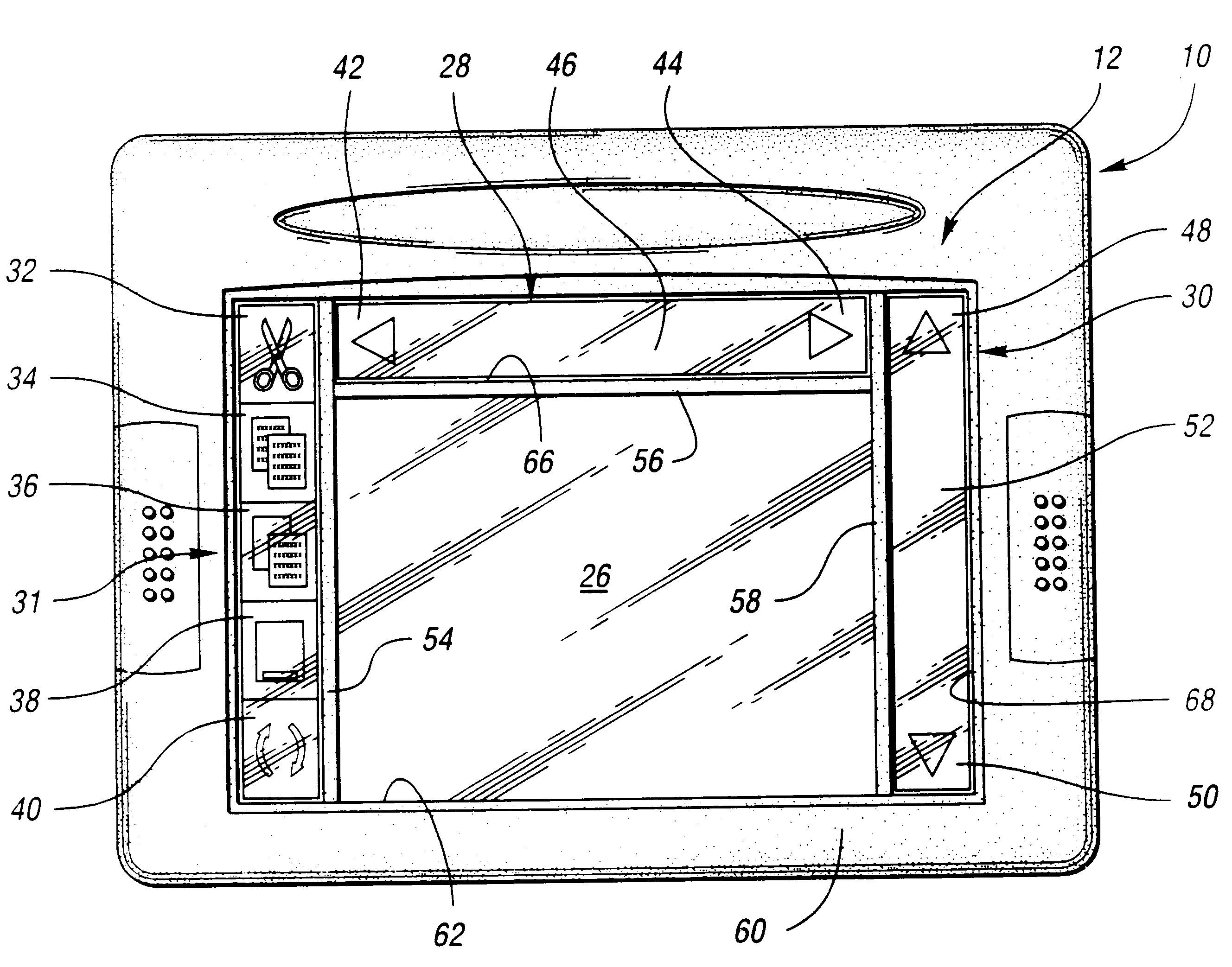
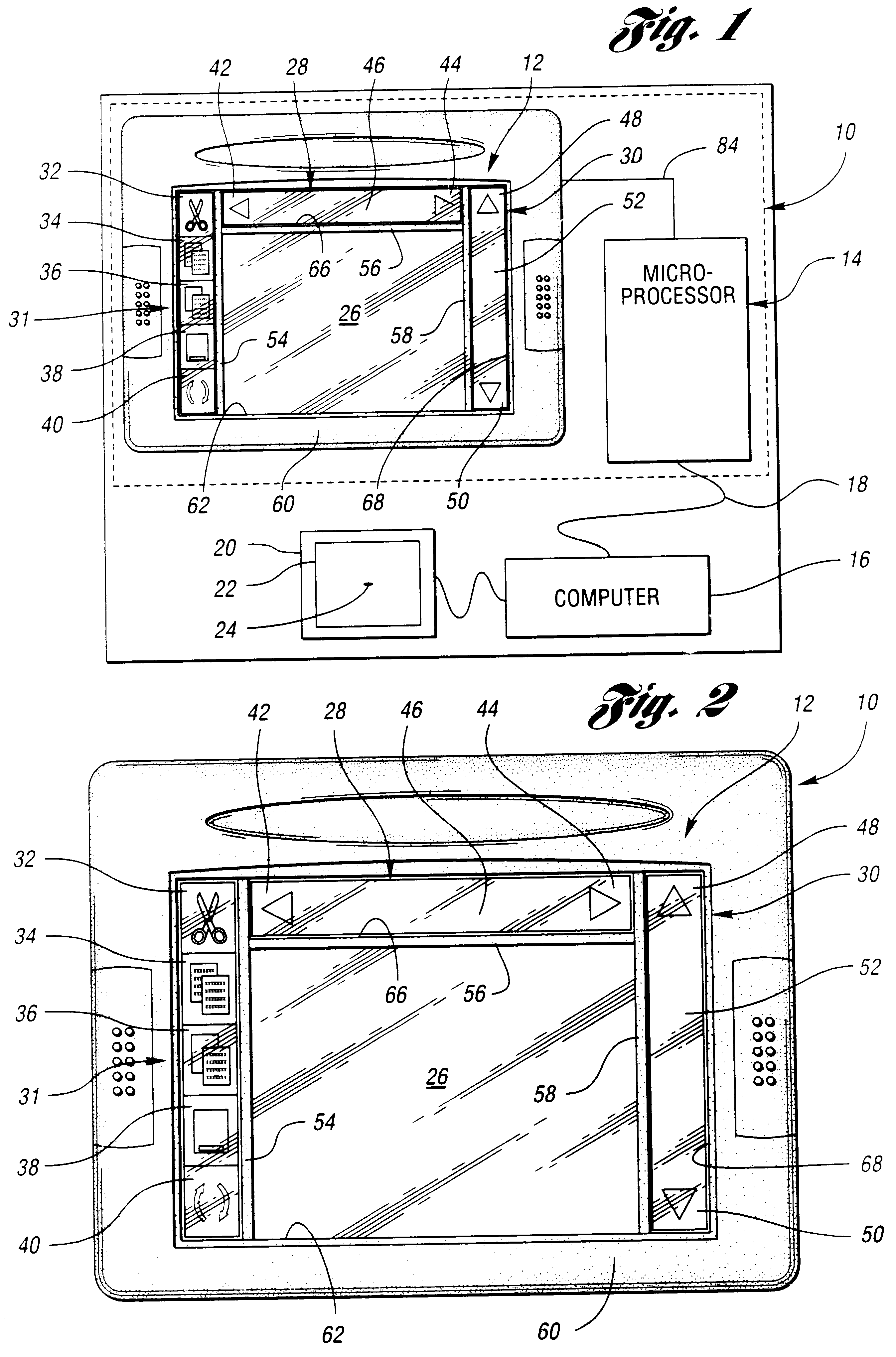
Referring now to FIGS. 1 and 2, a force sensing semiconductive touchpad assembly 10 of the present invention is shown. Touchpad assembly 10 is a touch-sensitive user input device. Touchpad assembly 10 includes a touchpad 12 and a microcontroller 14. Touchpad assembly 10 provides information indicative of the position of an operator's finger or stylus touching touchpad 12 to a computer 16 through a communications link 18. Touchpad assembly 10 also provides information indicative of the actual amount of pressure applied by an operator on touchpad 12. Computer 16 processes the information to control functions of a graphical user interface 20 producing a display 22 having a cursor 24. An operator may also select commands or manipulate graphically portrayed objects in graphical user interface 20 with touchpad assembly 10. Preferably, touchpad assembly 10 is built into a computer keyboard and positioned below the space bar of the keyboard so that an operator can manipulate touchpad 12 wit...


PUM


Abstract

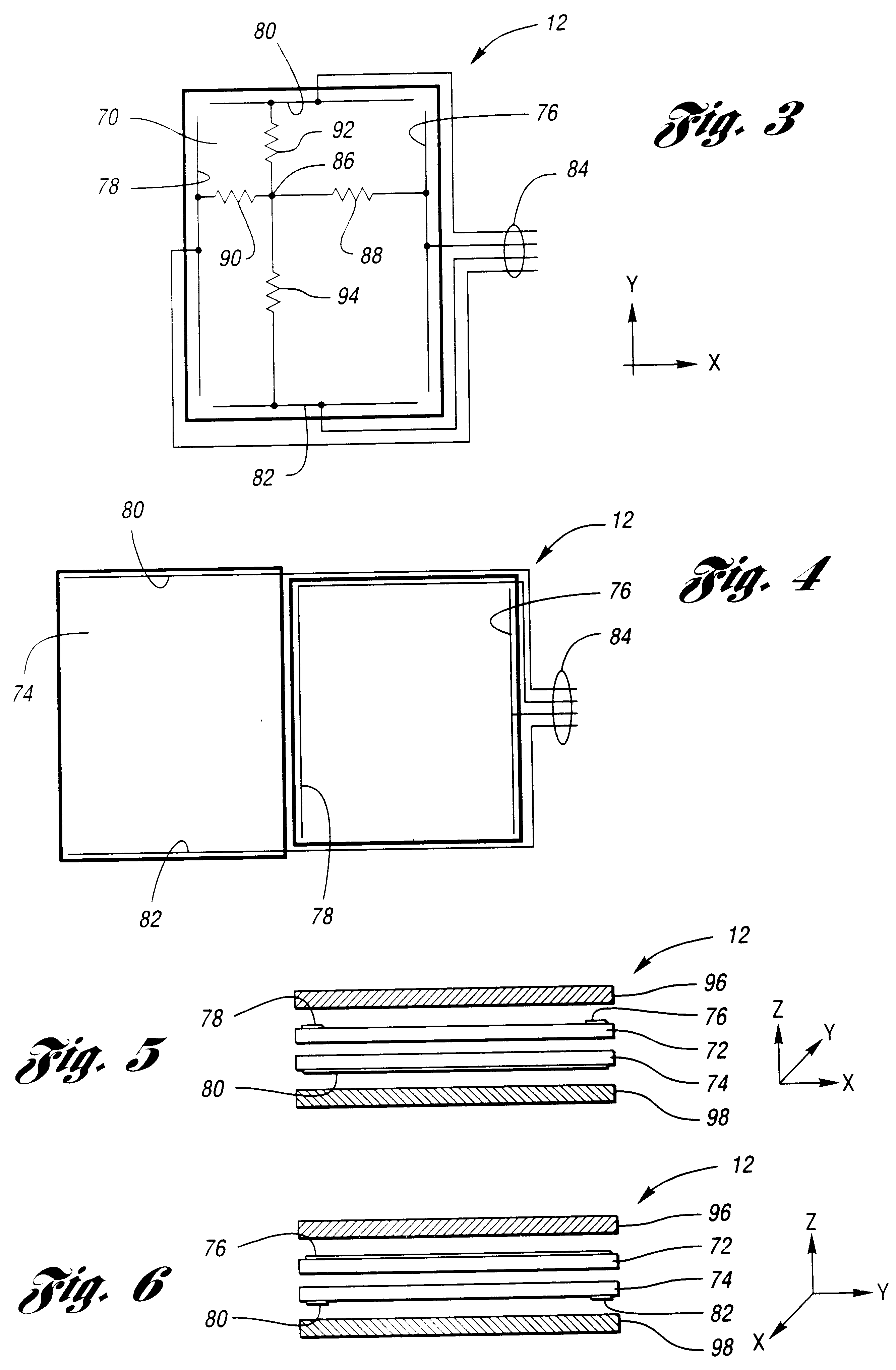
A touchpad assembly and method for providing a signal to a computer indicative of the location and applied pressure of an object touching the touchpad assembly is provided. The touchpad assembly includes X and Y position and pressure sensitive semiconductor resistance sensor layers. The X and Y sensors have a pair of spaced apart X and Y conductive traces running across opposite ends such that a resistance RX connects the pair of X traces and a resistance RY connects the pair of Y traces. The X and Y sensors come into contact at a contact point when an object asserts a pressure on the touchpad. The contact point is connected to each trace by a variable pressure resistance RZ associated with the X and Y sensors and variable position resistances of the X and Y resistances. First and second pair of timing capacitors are connected to respective ones of the pairs of X and Y traces. A microprocessor controls and monitors charging time of the capacitors to determine the position and asserted pressure of the object touching the touchpad.

Description

The present invention relates generally to object position sensing transducers and systems and, more particularly, to semiconductive touchpads.Numerous devices are available as object position detectors for use in computer systems and other applications. The most familiar of such devices is the computer mouse. While extremely popular as a position indicating device, a mouse has mechanical pans and requires a surface upon which to roll its position ball. The mouse translates movement of the position ball across the rolling surface as input to a computer. The growing popularity of laptop or notebook computers has created a significant problem for mouse type technologies which require a rolling surface. Laptop computers are inherently portable and designed for use in small confined areas such as, for example, airplanes, where there is insufficient room for a rolling surface. Adding to the problem is that a mouse usually needs to be moved over long distances for reasonable resolution. F...

Claims


Application Information

Patent Timeline
IPC IPC(8): G06F3/033G06F3/038G06F3/041
CPCG06F3/03547G06F3/038G06F3/041G06F3/0414G06F3/045G06F3/0488
Inventor MARTINELLI, JOHN K.MARTINELLI, ROBERT M.PICKETT, MARK C.RITCHEY, WENDELL W.YANIGER, STUART J.
Owner INTERLINK ELECTRONICS
Learn More