Dynamic delivery line mixing apparatus and method
a technology of mixing apparatus and delivery line, which is applied in the direction of transportation and packaging, rotary stirring mixers, and other chemical processes, can solve the problems of reducing the efficiency of the spray system, and increasing the settling ra
- Summary
- Abstract
- Description
- Claims
- Application Information
AI Technical Summary
Benefits of technology
Problems solved by technology
Method used
Image

Examples
example 1
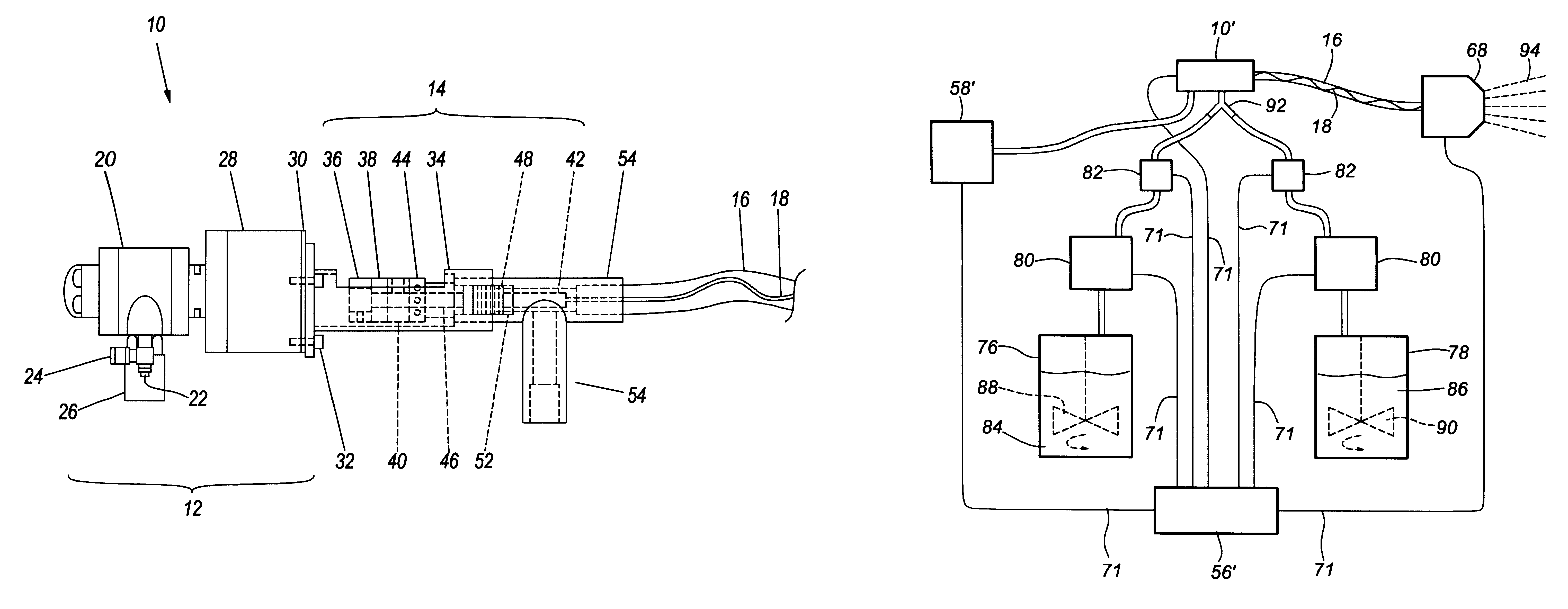
Acomparison was made between the first preferred embodiment of the coating system of the present invention as described above with reference to FIG. 5, and a control coating system. The control coating system was an identical coating system absent the operation of the in-line agitator. The comparison included two runs, and in both runs, the discharge end of the 28 foot delivery conduit was elevated to approximately 6 feet above floor level, while the opposite end of the delivery conduit was maintained at about floor level. As a result, the solid material within the feedstock naturally gravitated toward the floor within the delivery conduit, thus making it more difficult to prevent settling in the first run.
A well mixed feedstock suspension was maintained in a constantly agitated supply reservoir or pressure pot. The feedstock contained a solid known to quickly settle out of the suspension prior if to delivery from the spray gun. More specifically, the feedstock contained a specialty...
PUM
 Abstract
Description
Claims
Application Information
 - R&D
- Intellectual Property
- Life Sciences
- Materials
- Tech Scout
- Unparalleled Data Quality
- Higher Quality Content
- 60% Fewer Hallucinations
Browse by: Latest US Patents, China's latest patents, Technical Efficacy Thesaurus, Application Domain, Technology Topic, Popular Technical Reports.
© 2025 PatSnap. All rights reserved.Legal|Privacy policy|Modern Slavery Act Transparency Statement|Sitemap|About US| Contact US: help@patsnap.com