
Shaped bridge slapper

a bridge slapper and shaped technology, applied in the direction of electric fuzes, weapons, ammunition fuzes, etc., can solve the problems of secondary explosive detonation, explosive detonation, slap into an explosive, etc., and achieve the effect of reducing or different thickness and/or material

Inactive Publication Date: 2001-05-22
EXCELITAS TECH +1
View PDF6 Cites 54 Cited by
  • Summary
  • Abstract
  • Description
  • Claims
  • Application Information

AI Technical Summary

Benefits of technology

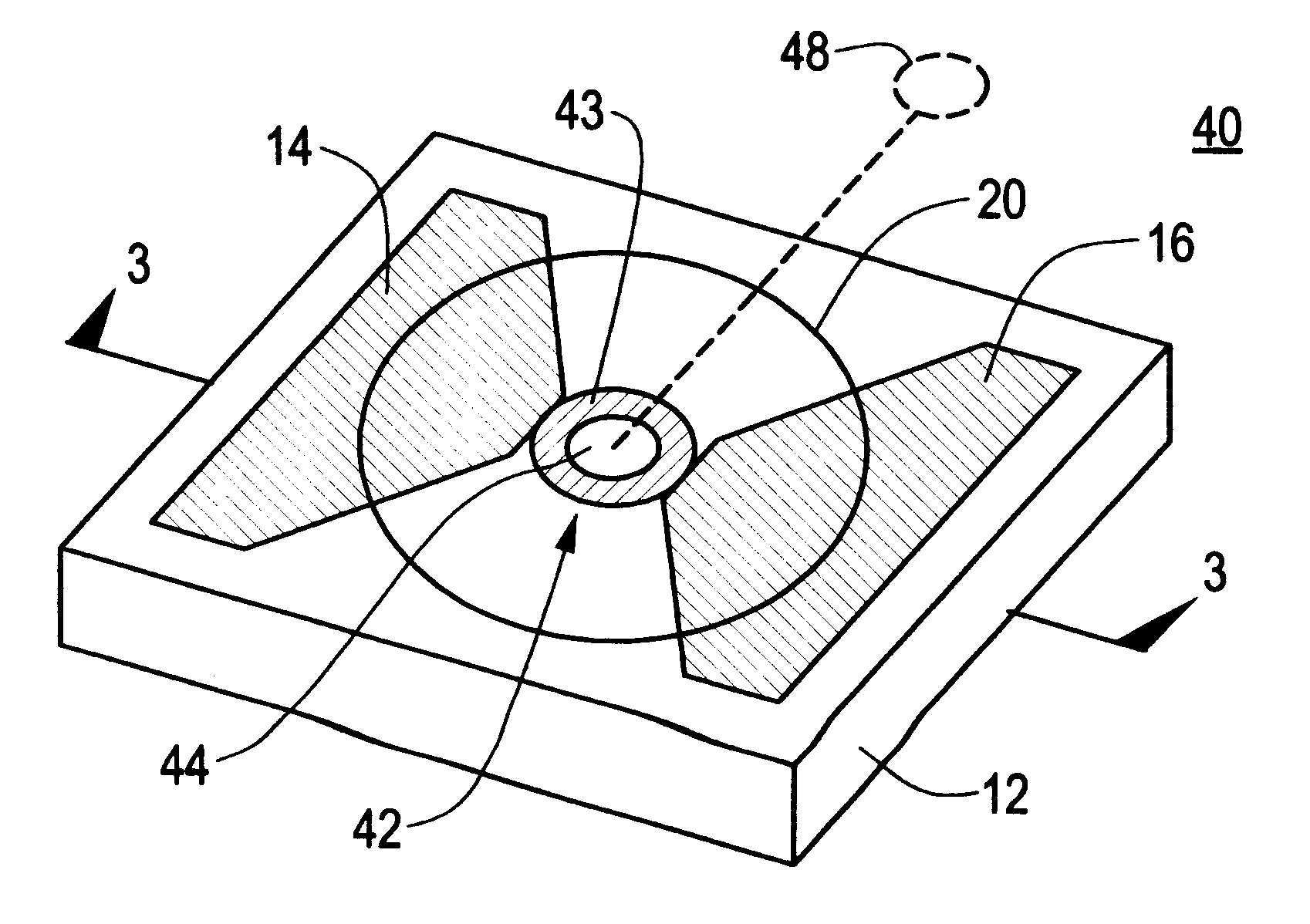
More broadly, this invention features a shaped bridge slapper comprising a substrate, a pair of spaced conductive lands on the substrate, a bridge member between the spaced conductive lands, the bridge member having a curved shape, and a flyer layer extending over the bridge member. Therefore, in this design there is no cavity of any kind in the bridge member. Alternatively, the shaped bridge slapper comprises a substrate, a pair of spaced conductive lands on the substrate, a bridge member between the spac...

Problems solved by technology

Slapper type detonators in general cause a "flying plate" to be propelled at a high velocity against a secondary explosive medium creating a shock wave which results in the detonation of the secondary explosive.
This plasma accelerates a portion of the dielectric material covering the bridge member to a high velocity, causing it to slap into an explosive.
The resulting shock wave causes detonation of the explosive.
It has been discovered by the inventor of the subject invention, however, that this rectangular shape results in adverse edge effects which render the detonator inefficient.

Method used


Image

  • Shaped bridge slapper
  • Shaped bridge slapper
  • Shaped bridge slapper

Examples


Embodiment Construction

Other objects, features and advantages will occur to those skilled in the art from the following description of a preferred embodiment and the accompanying drawings, in which:

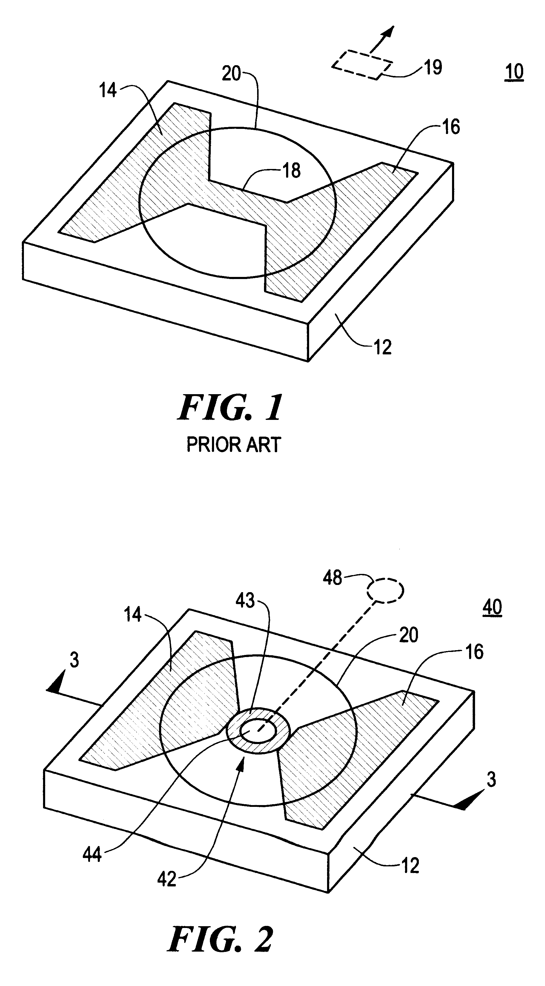
FIG. 1 is a perspective view of a prior art chip slapper detonator;

FIG. 2 is a perspective view of the shaped bridge slapper in accordance with the subject invention;

FIG. 3 is a cross-sectional view of the chip slapper of the subject invention taken along the line 3--3 in FIG. 2;

FIG. 4 is a cross-sectional view of another embodiment of the chip slapper of the subject invention;

FIG. 5 is a cross-sectional view of another embodiment of the shaped bridge slapper of the subject invention; and

FIG. 6 is a perspective view of another embodiment of the shaped bridge slapper of the subject invention.

Conventional "chip" slapper 10, FIG. 1 includes ceramic substrate 12 upon which is deposited metal film such as copper etched into the shape of spaced conductive lands 14 and 16 and rectangular bridge member 18 extending the...


PUM


Abstract

A shaped bridge slapper having a pair of spaced conductive lands on a substrate; a bridge member between the spaced conductive lands, the bridge member having a curved shape and a cavity herein, and a flyer layer extending over the bridge member.

Description

This invention relates generally to devices for setting off an explosive charge and more particularly to a slapper type detonator with a shaped bridge member.BACKGROUND OF INVENTIONSlapper type detonators in general cause a "flying plate" to be propelled at a high velocity against a secondary explosive medium creating a shock wave which results in the detonation of the secondary explosive. In a typical design, there are two wide area conductive lands separated by a narrow rectangular bridge member. The lands are connected to a capacitor through a high voltage switch. When the switch closes, the capacitor provides current across the lands which vaporizes the bridge member turning it into a plasma. This plasma accelerates a portion of the dielectric material covering the bridge member to a high velocity, causing it to slap into an explosive. The resulting shock wave causes detonation of the explosive.Conventional slappers have a rectangular bridge which results in rectangular flying p...

Claims


Application Information

Patent Timeline
IPC IPC(8): F42B3/12F42B3/00
CPCF42B3/124
Inventor NEYER, BARRY T.
Owner EXCELITAS TECH
Learn More