
Marine vibrator

Inactive Publication Date: 2001-05-15
WESTERNGECO LLC
View PDF2 Cites 78 Cited by
  • Summary
  • Abstract
  • Description
  • Claims
  • Application Information

AI Technical Summary

Benefits of technology

In certain embodiments, the present invention provides a marine vibrator with a hollow hull formed of one or more shells that define an inner space therein and have a streamlined shape for reducing hydrodynamic drag.
The present invention, in certain embodiments, discloses a submersible marine vibrator with a hull made of one or two outer shells. In one aspect there are two shells that differ in shape, e.g. two shells with different curvatures or a curved shell and a relatively flat shell. In another aspect there are two matching outer shells, each shell having a relatively flat curved shape, in one aspect defining a spherical segment of one base. In multi-shell embodiments, the edges of shells may be joined by a flexible seal or flexible connector. In embodiments using either two shells or a single shell, one or more stress relief recesses, slots, or slot portions may be used around all or a portion of a shell. In certain aspects for streamlining to reduce hydrodynamic drag, the surfaces of the shell or shells are defined by a radius which is significantly greater than the diameter of a base of the shells.

Problems solved by technology

Existing prior art marine vibrators do not achieve these power levels in the low end of the seismic spectrum.
Several existing prior art units may be used in concert to achieve the desired acoustic power in the seismic frequency band; but simultaneous use of multiple marine vibrator units complicates deployment, towing, synchronization, and operation.
Many prior art marine vibrators used in seismic survey operations minimize the enclosed volume of the device which results in strong negative buoyancy.

Method used


Image

  • Marine vibrator
  • Marine vibrator
  • Marine vibrator

Examples


Embodiment Construction

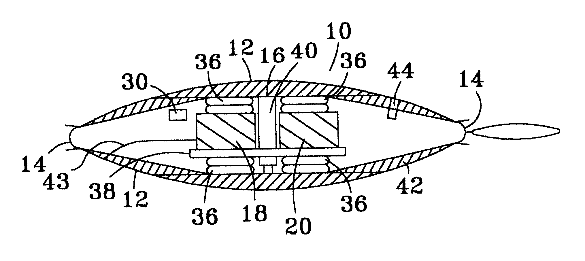
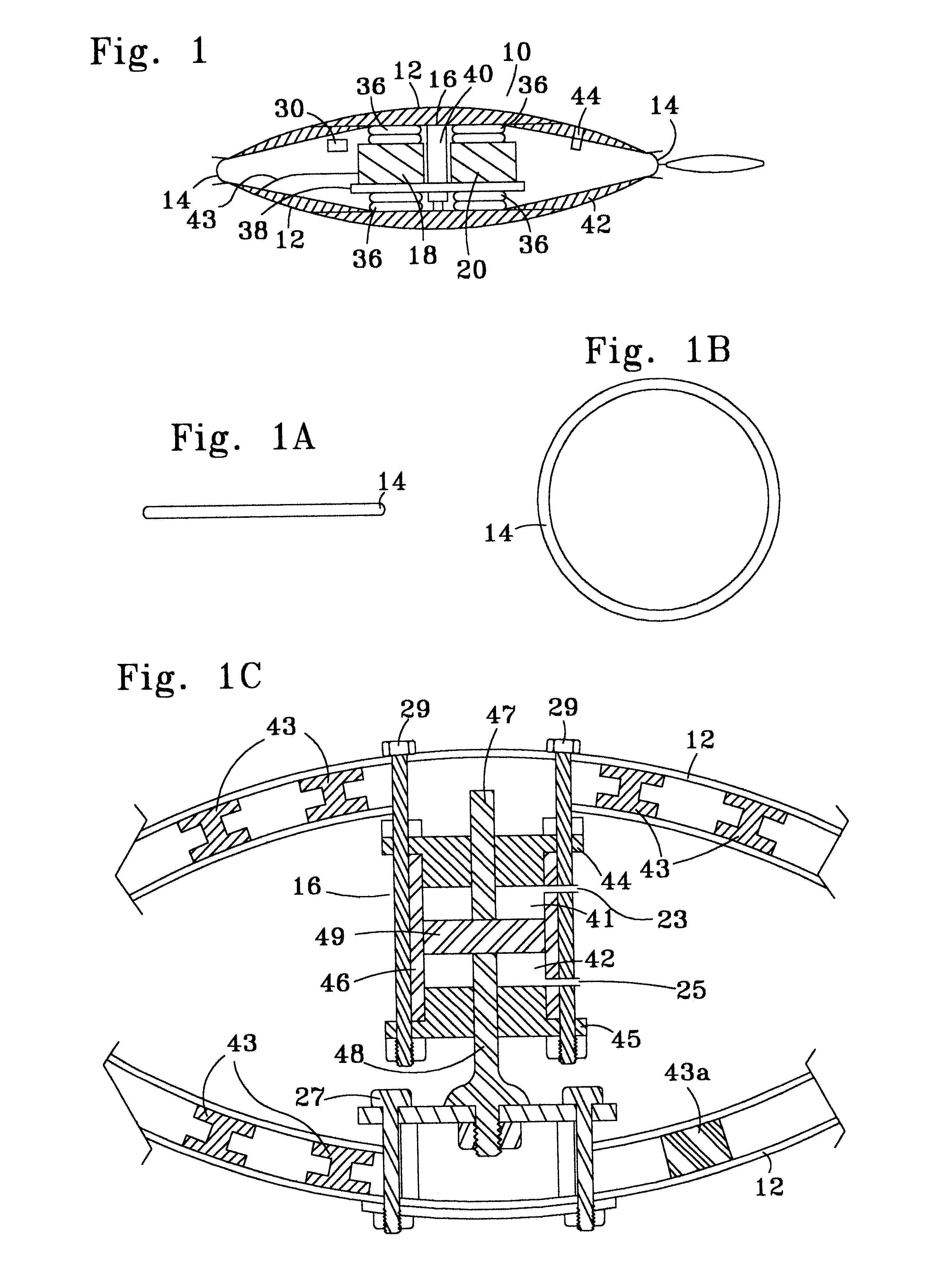
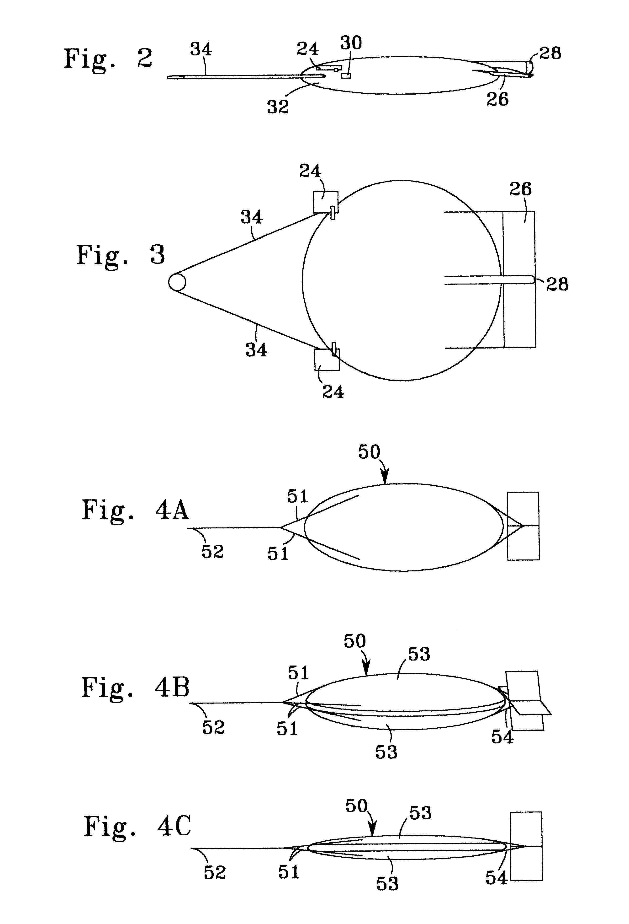
Referring now to FIGS. 1-3, marine vibrator 10 has two outer shells 12 which are connected together by a flexible member or seal connector 14 to which the shells are attached by glue, sealing compound, and / or bolts. The shells 12 are, optionally, reinforced with steel 42 and, optionally, with I-beams. The reinforced shells define an inner space that is, in one aspect, filled with gas such as air under pressure (e.g. introduced through a valve 44) to compensate for exterior water pressure when the vibrator 10 is submerged. The shells 12 may be made of any suitable material of sufficient strength for use in the intended marine environment, including, but not limited to metal, fiberglass, plastic, and mixtures and combinations thereof.

Vibrator system 16 is positioned within the shells 12 so that equal and opposite force is applied to each shell 12 when the vibrator system 16 is activated. The vibrator system, in certain aspects, includes an electrically driven hydraulic pump 18 and an ...


PUM


Abstract

A marine vibrator has a hollow body formed of one shell or of two opposed shells defining an inner space therein with vibrator apparatus within the hollow body. At least one shell has a curved shape, and the shell can have a streamlined shape with relatively low hydrodynamic drag. Certain embodiments include one or more exterior control members to facilitate positioning of the vibrator in water. Other than their mating ends, when two shells are used the two shells may be different in shape and volume or they may be identical. In preferred two-shell embodiments, there is a flexible seal between and connecting the two opposed shells. In certain aspects the inner space is filled with gas. A vibrator apparatus in one aspect applies equal and opposite forces to the shells of a two-shell vibrator or to opposed sides of a single shell vibrator.

Description

1. Field of the InventionThis invention is directed to marine vibrators used in marine seismic systems. In particular, the invention is related to low frequency acoustic sources used in marine seismic surveys.2. Description of Related ArtThe prior art discloses a variety of marine vibrators (or underwater acoustic projectors) used in marine seismic surveys, including but not limited to U.S. Pat. Nos. 3,329,930, 3,384,868, 3,392,369, 3,394,775, 3,482,646, 3, 676,840, 4,853,905, and 4,885,726. Prior art vibrator devices have a variety of shapes ranging from cylindrical to bell-shaped to spherical. Operationally, these devices are sufficiently heavy so that they do not float and sink of their own accord.The prior art discloses various underwater acoustic projectors (e.g. as in U.S. Pat. Nos. 3,875,552, 5,247,894 and 5,600,087) used in submarine warfare. These devices are streamlined, generally neutrally buoyant, have control systems which facilitate changing depth, course and speed, an...

Claims


Application Information

Patent Timeline
IPC IPC(8): B63G8/00B63G8/42G01V1/02G01V1/145G01V1/38
CPCB63G8/001B63G8/42G01V1/02G01V1/145G01V1/38
Inventor AMBS, LORAN D.
Owner WESTERNGECO LLC
Learn More