
Pivotable gutter assembly and kit therefor

a technology of gutter assembly and kit, which is applied in the direction of machine supports, household objects, applications, etc., can solve the problems of water back-up and flow over the edge of the gutter, the accumulation of leaves, rubbish and bird's nests in the gutter, and the partially clogged gutter giving unsatisfactory services

Inactive Publication Date: 2001-05-22
OBIDNIAK LOUIS
View PDF22 Cites 24 Cited by
  • Summary
  • Abstract
  • Description
  • Claims
  • Application Information

AI Technical Summary

Benefits of technology

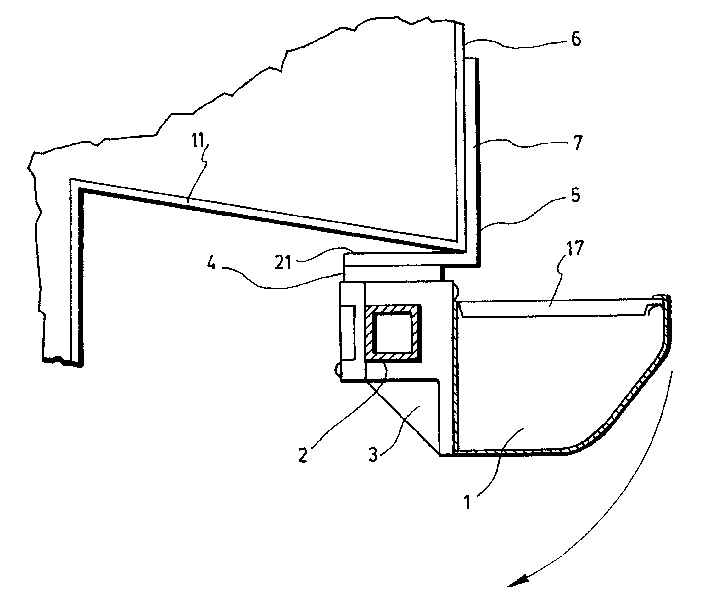
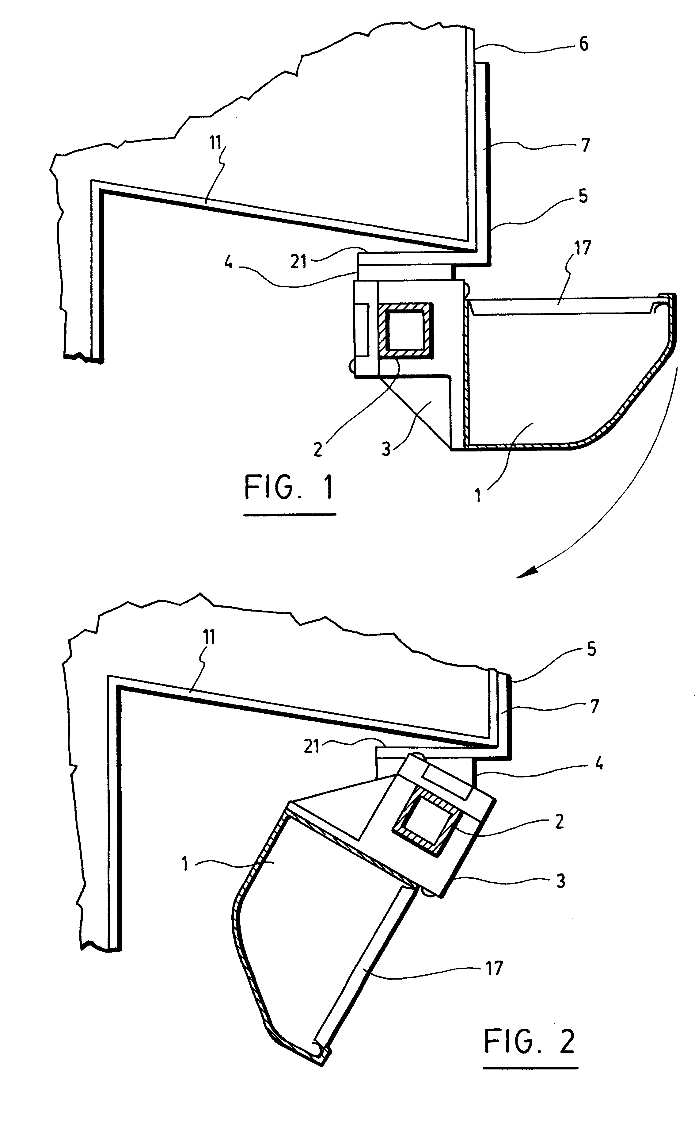
The gutter assembly is pivoted between an operative position, where the gutter is adjacent and below the roof in order to collect rainwater and direct it to the down-spout for evacuation, to an inoperative position, where the gutter is at least at a 90.degree. angle with respect to the operative position, in order to permit easy cleaning of the gutter with a stream of water. This position can also be used to "hide" the gutter under the roof during the winter months so that there is no accumulation of water (and ice) or other debris therein, which would otherwise damage the gutter, or cause damage to the roof or to the walls of the house.
Preferably, the hangers have a fixed length and lowered by a distance between L and L+X, so that the hangers are installed from one end of the fascia to the other end of the fascia with a gradually increasing (or decreasing) distance from fascia, as the case may be, as long as the down-spout of the gutter is located adjacent the lowest gutter position (having a length L+X). This gradual increase in hanger position gives the shaft, and therefor the gutter, a downward pitch, permitting easier evacuation of the water. Preferably, the hangers are sold as a set with a predetermined length, so that the homeowner can easily install the hangers by following indicia printed thereon and lower the hanger from position L (X=0 ) to L+X.

Problems solved by technology

Leaky, damaged and partially clogged gutters give unsatisfactory services, and can also be a direct cause of other more serious troubles, such as water getting in the attic or seeping into the walls near the cornices.
Difficulty may arise from the accumulation of leaves, rubbish and bird's nests in gutters.
Such debris, if not promptly removed, may clog the opening to the down-spout and cause the water to back-up and flow over the edge of the gutter.
Even if leaf guards or strainers have been installed at the down-spout opening, an accumulation of wet leaves will prevent proper drainage and may cause water to overflow and seep into walls of the house.
If the gutters are not fitted with leaf strainers, leaves may accumulate in the gutter system and completely close the passage to water.
In cold weather, water may accumulate and freeze in clogged down-spouts.
The accumulated snow and ice in the gutter will prevent, during the spring thaw, the roof run-off from being properly drained, and water may seep into the roof and wall of the house, causing considerable and expensive damage to the roofs and wall structures near the cornice.
Also, water may collect and freeze in clogged elbows and down-spouts, causing considerable damage to these parts due to the expansion of the water when it freezes.
However, it is not easy to clean the presently installed gutters.
These cleaning procedures are not only difficult but can also be dangerous, and often homeowners will call upon professionals to clean the gutters, which can be costly.
Gutters which are not regularly cleaned will deteriorate and will require replacements, and also will cause damage to the fascia and to the cornices and wall of the house.
However, those devices do not disclose a mechanical construction which can adequately and completely empty the gutter.
The disclosed mechanisms are exposed to weather elements and would become inoperative should ice accumulate in or on the moving parts.
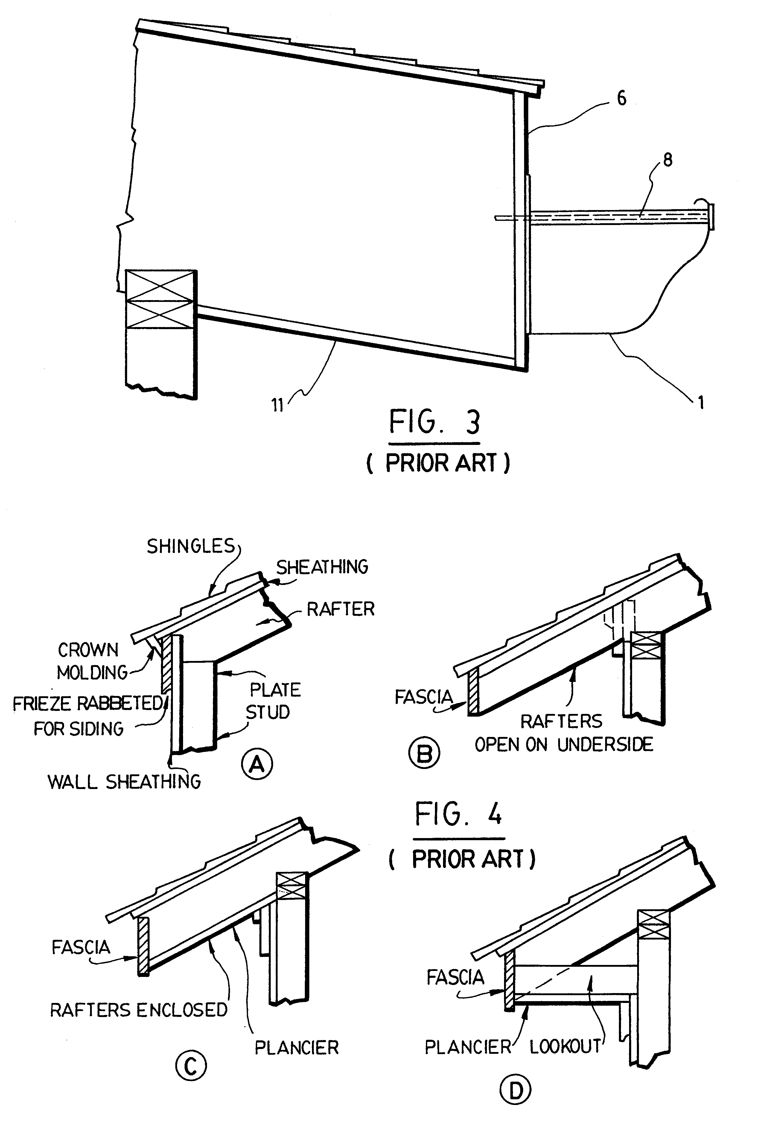
A significant absence in the prior art is the lack of any description regarding the gutter pitch, i.e. the slope of the gutter which permits water to drain downwardly, and also how those gutters are disconnected from the down-spout when the gutter is pivoted from the horizontal to the vertical position.
Most of the above-mentioned prior art devices require, to move the gutter from one position to another, a step ladder to reach the moving mechanism, which can be a complicated and dangerous operation, particularly when the gutters are at a substantial distance above ground level, as is the case with highrise buildings.

Method used


Image

  • Pivotable gutter assembly and kit therefor
  • Pivotable gutter assembly and kit therefor
  • Pivotable gutter assembly and kit therefor

Examples


Embodiment Construction

The pivotable gutter system according to the invention comprises as its main elements a plurality of hangers 5, each having a bearing 4, a shaft 2 rotatably mounted in the bearings 4, a gutter 1 mounted on the shaft 2 and means to pivot the shaft 2.

Referring now to FIG. 1, the shaft 2, which is preferably square, is mounted in the bearings 4 of the hangers 5. As can be seen, the hangers have a vertical leg 7 which is fastened to the fascia of the roof, for reasons which will be explained hereinafter, and a bottom 21, in the shape of a horizontal leg. The gutter 1 is attached to the shaft 2 through a bracket 3 mounted on the shaft 2 at regular intervals. The bracket also includes a holding bracket 17 which is wrapped around the gutter and which is attached to the bracket 3 (see FIG. 8A and FIG. 8B). The brackets are movable along the square shafts for proper positioning during assembly and then tightened by a screw to lock it in position. The brackets 3 are usually disposed every 3 t...


PUM


Abstract

A pivoting gutter assembly is disclosed, in which the gutter can be, during summer months, put into the horizontal collecting position to receive rainwater from the roof and to direct it to a down-spout. For the winter months and or maintenance, the gutters are swung-out to downwards vertical position below the roof cornice thus being protected from damage. The gutter system includes hangers attached to the roof, the hangers each having a bearing. A shaft is inserted into the bearing and the gutter is fixed to the shaft. The system provides for special hangers assuring the correct pitch of the gutters. Also, it contains a down-spout for location above a fixed downward collector for rainwater, thus permitting the gutters to be pivoted from horizontal to vertical position without the need to disconnect the down-spout. A wormgear and wormdrive are attached to the end of shaft, outside the house fascia; this drive permits to operate the gutter's position from the ground level by an extended bar and manually driven crank or by using electric motor's drive attached to worm and remote control, eliminating the need of a ladder to reach downward position particularly important for the gutters installed on the roof high above the ground such as high rise buildings.

Description

The present invention relates to a pivotable gutter assembly and a kit for the same. The gutter assembly is pivoted to a horizontal position to receive the rainwater falling from the roof and direct the rainwater to down-spout to evacuate it away from the house. The pivotable gutter assembly can be pivoted to a vertical position in order to permit cleaning thereof, or to hide the gutter assembly under the roof's cornice in the winter months.DESCRIPTION OF THE PRIOR ARTIt is estimated that on average, 5000 gallons of rainwater fall on the roof of a typical house in Canada, during a year. To collect this rainwater from the roof, a system of gutters and down-spouts are installed, and permanently affixed to the roof cornice's fascia plate, and to the house. It should be understood at the outset that the word "house" is intended to include any structure having a roof and which requires a gutter system to evacuate the water therefrom. Likewise, the expression "homeowner" is meant to inclu...

Claims


Application Information

Patent Timeline
Patent Type & Authority Patents(United States)
IPC IPC(8): E04D13/04E04D13/076E04D13/072E04D13/064
CPCE04D13/064E04D13/0641E04D13/0727E04D13/076
Inventor OBIDNIAK, LOUIS
Owner OBIDNIAK LOUIS
Learn More