
Charging controller

a charging controller and controller technology, applied in electric power, electric vehicles, transportation and packaging, etc., can solve the problems of large surplus power supply capability of dc power, increased shape and size of dc source, and ineffective use of surplus power of dc sour

Inactive Publication Date: 2001-05-08
MURATA MFG CO LTD
View PDF3 Cites 67 Cited by
  • Summary
  • Abstract
  • Description
  • Claims
  • Application Information

AI Technical Summary

Problems solved by technology

In FIG. 5, the maximum power required to drive the unit is 30 W, and the maximum charging power is 30 W. Accordingly, the supply capability of the dc source is 60 W. However, since the power required to drive the device is changed with time, a large part of the power supply capability of the dc power is surplus.
Thus, there arises the problem that the shape and size and the cost of the dc source are increased.
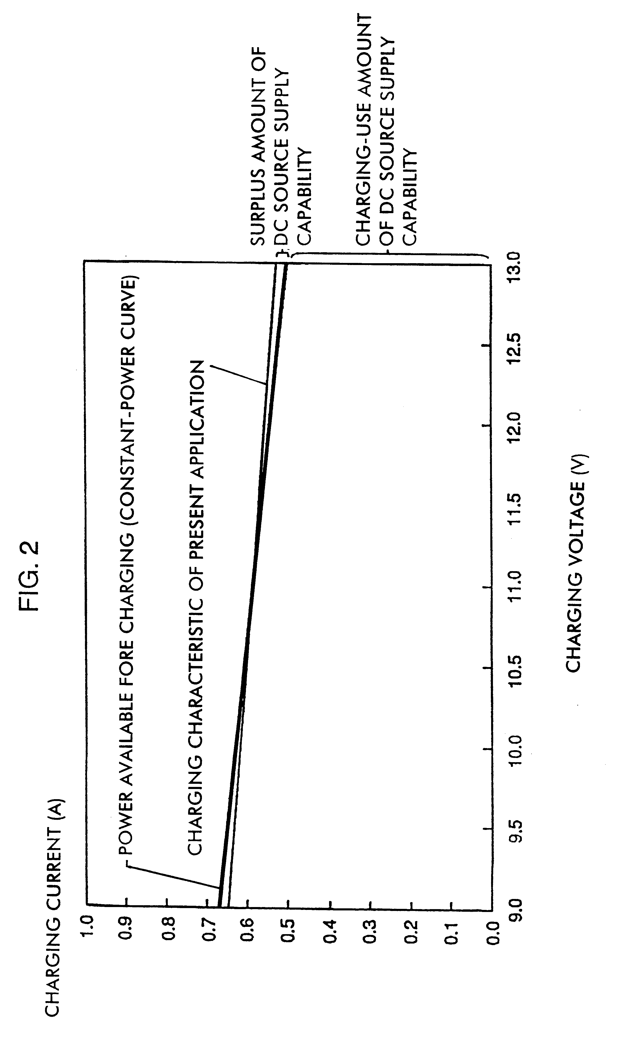
However, since the charging current is kept constant, irrespective of the charging voltage, the surplus power of the dc source can not effectively be used.
Accordingly, if the charging is carried out in this technique, the power supply capability of the dc source becomes surplus when the charging voltage is low.
Accordingly, in the second technique of the conventional example, the power supply capability of the dc source can not effectively be used.
Thus, there arises the problem that the charging time is increased, in spite of the power supply capability of the dc source.
Therefore, a loss and heat generated in the dc source output current detection resistor 5 are increased, the reliability of the circuit is reduced, and the current detection accuracy deteriorates, caused by effects on the temperature characteristic of the dc source output current detection resistor 5.
Moreover, it is needed to take heat dissipation measures such as attachment of a radiation plate, which causes the problem that the shape and size, and the cost of the charging circuit are increased.

Method used


Image

  • Charging controller
  • Charging controller
  • Charging controller

Examples


Embodiment Construction

Hereinafter, the preferred embodiments of the present invention are explained in detail with reference to the drawings.

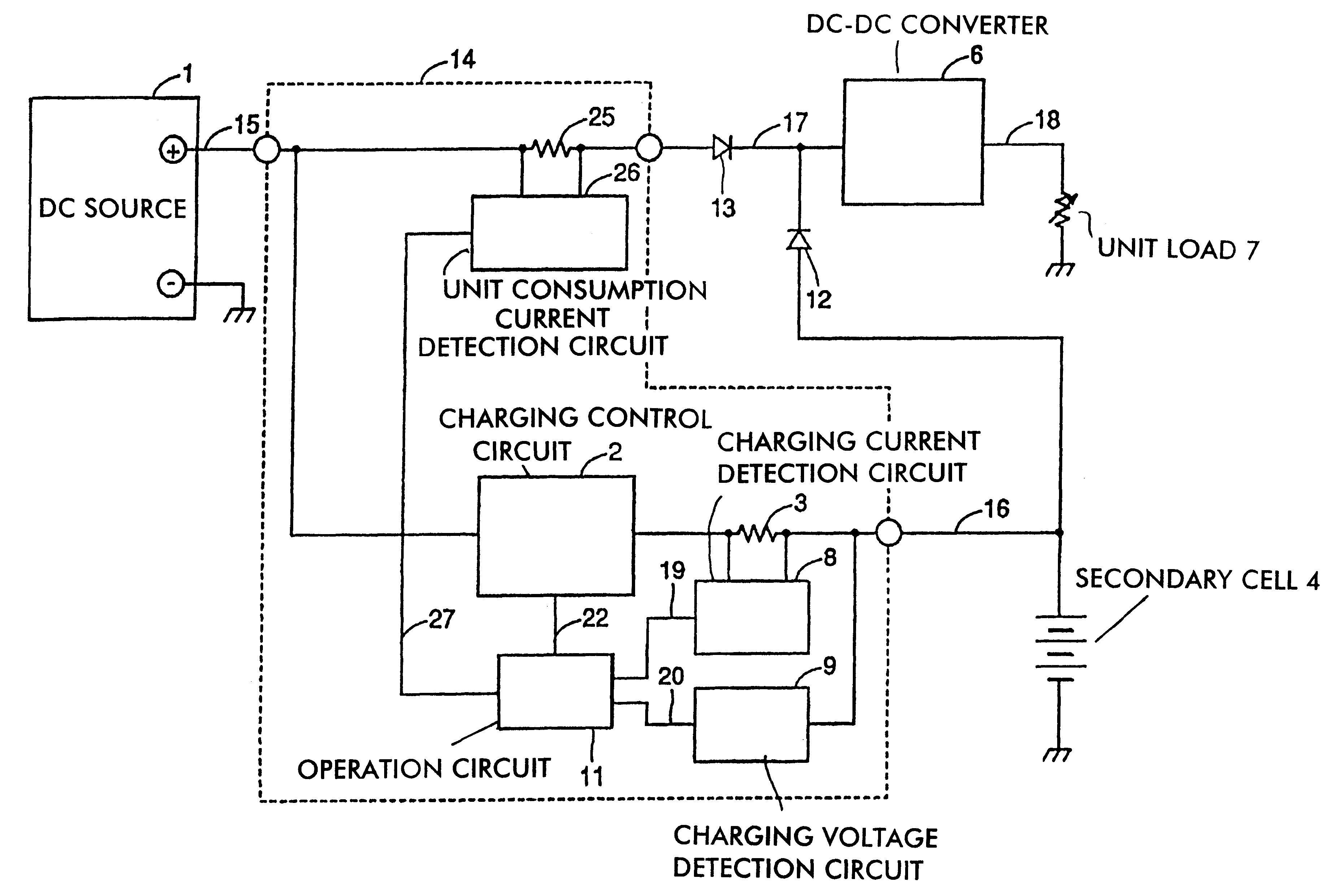
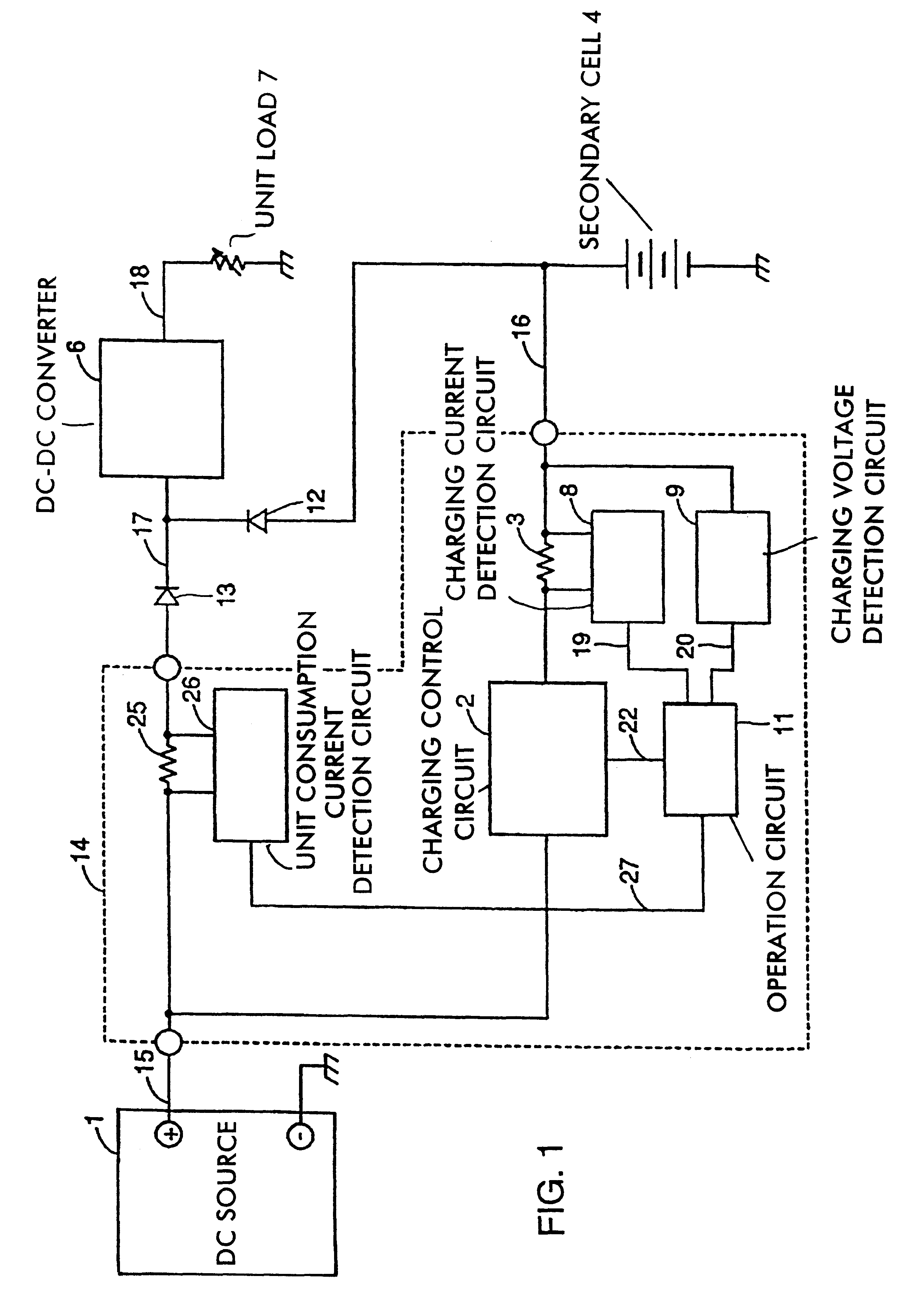
FIG. 1 is a block diagram of an embodiment of the present invention. In FIG. 1, parts which are configured differently from the configuration shown in FIG. 8 will be described. In this embodiment, a unit consumption current detection resistor 25 is provided instead of the dc source output current detection circuit 5 shown in FIG. 8, a unit consumption current detection resistor 26 is provided instead of the dc source output current detection circuit 10, and an operation circuit 11 is provided. To the operation circuit 11, a detection output 19 from a charging current detection circuit 8, a detection output 20 from a charging voltage detection circuit 9, and a detection output 27 from the unit consumption current detection circuit 26 are provided. The operation circuit 11, based on these detection outputs, calculates the charging power and the output power from a dc ...


PUM


Abstract

A charging controller for charging a secondary battery by a dc source has a consumption current detector detecting a consumption current of a load; a charging current detector detecting a charging current to the secondary battery; a charging voltage detector detecting a charging voltage to the secondary battery, a function-processor to which detection outputs from the consumption current detector, the charging current detector, and the charging voltage detector are provided, respectively, anda charging control circuit controlling a charging output to the secondary battery, based on calculation results by the function-processor such that driving the load and charging are simultaneously executed within the ratings of the dc source.

Description

1. Cross Reference to Related ApplicationThis application is one of four related applications, Ser. Nos. 09 / 566,445 , 09 / 566,930, 09 / 568,720 and 09 / 569,938.2. Field of the InventionThe present invention relates to a charging controller, and more particularly to a charging controller for charging a secondary battery used in a portable electronic device, for example.3. Description of the Related ArtPortable electronic devices such as a notebook-sized computer, and so forth contain a secondary battery. As to a charging controller for driving a unit and charging the secondary battery simultaneously, the following techniques have been disclosed.According to a first technique, the rating of output power from a dc source is designed so as to be not less than the sum of the maximum consumption power of a unit and maximum charging power.According to a second technique, as described in Japanese Unexamined Patent Publication No. 5-137276, only a unit load current is detected, the difference be...

Claims


Application Information

Patent Timeline
IPC IPC(8): H02J7/00H02J7/34H02J7/10
CPCH02J7/0068
Inventor TOKUYAMA, HIROSHI
Owner MURATA MFG CO LTD
Learn More