
System and method for generating a hazard-free asynchronous circuit

a technology of asynchronous circuit and generating system, which is applied in the direction of specific program execution arrangement, program control, instruments, etc., can solve the problems of circuits that have a wrong long-term response (races), violate the csc requirement, and always wrong long-term response circuits

Inactive Publication Date: 2001-05-01
INTERUNIVERSITAIR MICRO ELECTRONICS CENT (IMEC VZW)
View PDF7 Cites 20 Cited by
  • Summary
  • Abstract
  • Description
  • Claims
  • Application Information

AI Technical Summary

Problems solved by technology

Thus, there is a violation of the CSC requirement.
A hazard is a mal-function that appears during a transient response due to switching delays.
However, the pure delay model captures the worst case scenario for the propagation of a hazard through a logic network.
A circuit that has a wrong long-term response (races) is always wrong regardless of whether the circuit has no transient response glitches (hazards).
Unlike the conventional approaches, the SOP core itself can be hazardous.
These methods are limited to distributive semi-modular SGs, and, a solution is not guaranteed to exist.
The n-shot architecture shown in FIG. 5b is not speed independent, however, it is assumed that internal gates and wires can have any delays (wire forks are not required to be isochronic).
Using this approach, the SOP core can be hazardous.
If non-digital values are propagated, information loss may occur.
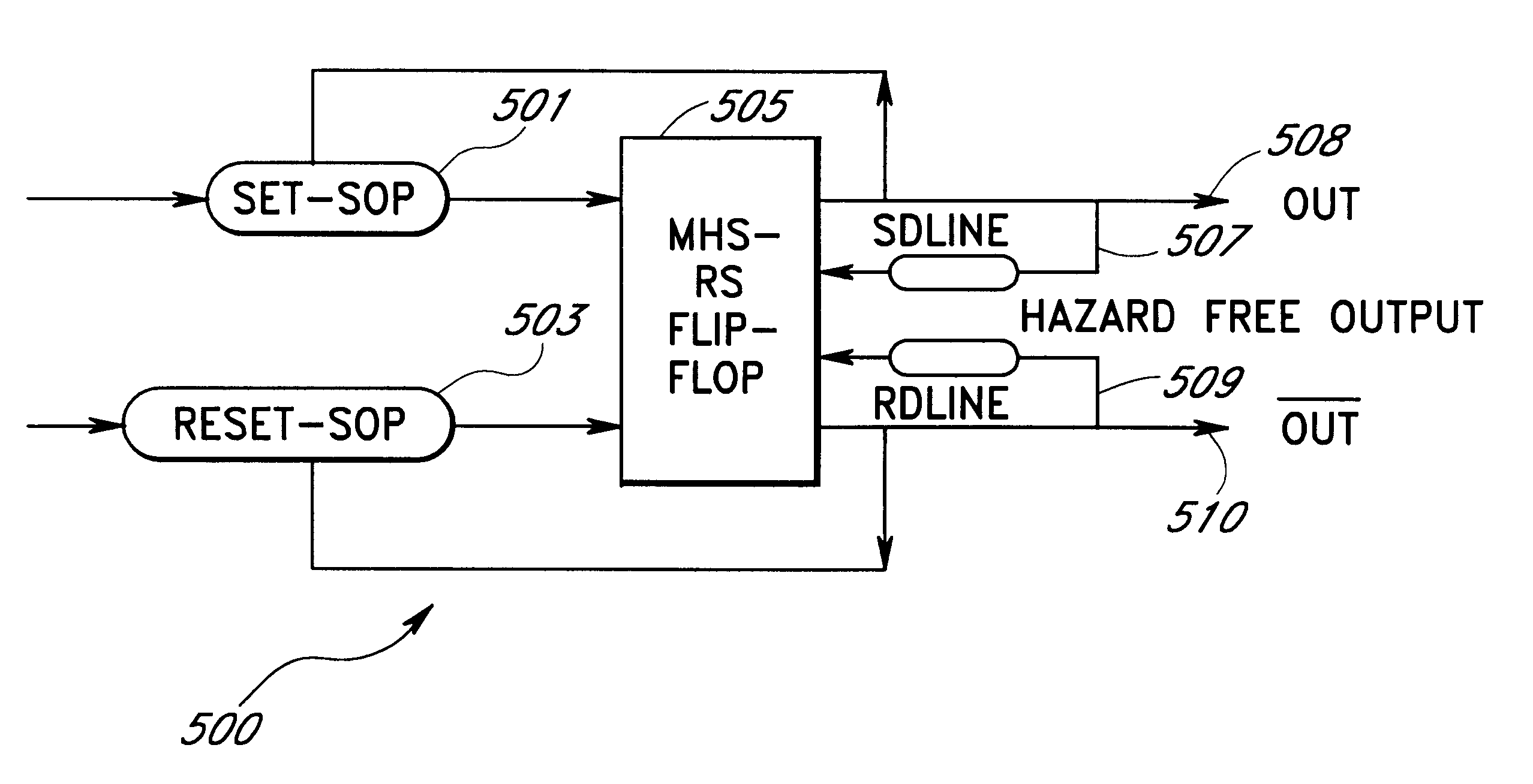
However, avoiding misfirings due to trespassing or spurious pulses cannot be solved by the MHS flip-flop alone, because the flip-flop depends on the SOP time responses.
As discussed above, since the SOP solution can be hazardous, it can functionally be treated as a synchronous circuit.
If the one-shot requirements are not satisfied940, then MC and HC will also fail.

Method used


Image

  • System and method for generating a hazard-free asynchronous circuit
  • System and method for generating a hazard-free asynchronous circuit
  • System and method for generating a hazard-free asynchronous circuit

Examples


Embodiment Construction

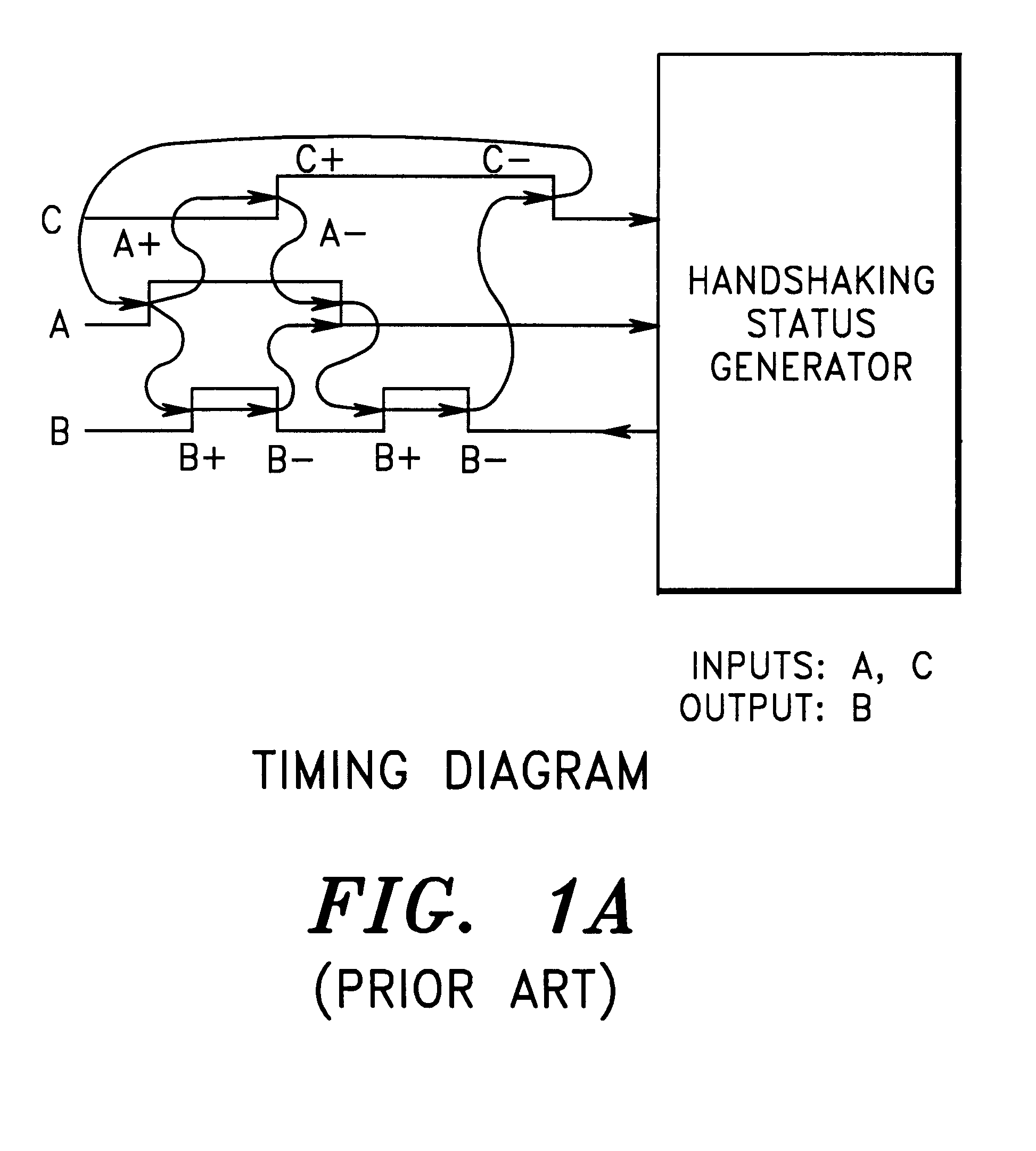
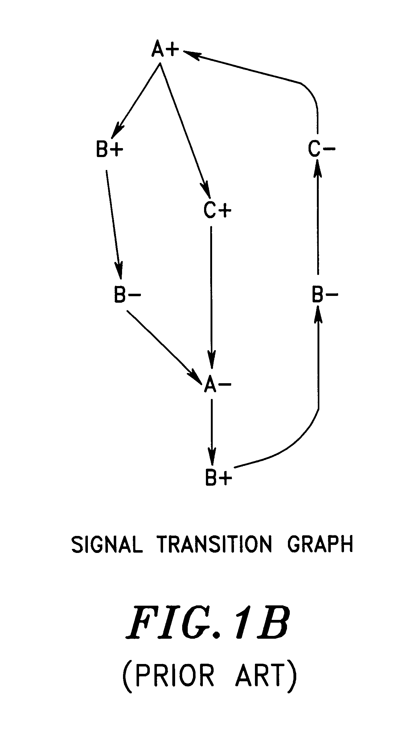
In FIG. 10a two processes A and B communicate such that process A is considered as the environment and process B the circuit to synthesize. Process B has inputs a, b, and d, and output signal c. FIG. 10b is an example semi-modular state graph with input choices that shows the excitation regions of signal c for the process in FIG. 10a. The input choices at states s.sub.-- 0, s.sub.-- 1, s.sub.-- 2 are made by process A. Although states s.sub.-- 0 and s.sub.-- 4 have the same codes, their next state behavior is decided by process A (thus there is no mutual exclusion). Thus, the SG satisfies CSC. Note that state 1100 is an unreachable state.

For each approach (HC, MC, one-shot, auto_C, n-shot), a Karnaugh map is shown that demonstrates how the conditions and requirements of the approach restrict the covering of the map.

A. The HC requirement

Under the hard cube (HC) requirement, a single cube to cover the entire ON-SET space of c (i.e., fire +c) is required. FIG. 10c is an example Karnaug...


PUM


Abstract

A flip-flop-based circuit architecture generates a hazard-free asynchronous signal given the SET and RESET sum-of-product (SOP) solutions to an asynchronous process. The flip-flop SET and RESET SOP solutions can be hazardous. Thus, general purpose synchronous optimization tools (which are indifferent to hazards) can be used to derive the optimal SOP solutions. A fixed layer built around the SOP cores eliminates all hazards in the circuit. In one embodiment, the architecture is optimized by eliminating an RS latch and delay lines in the SOP cores. The architecture of the present invention is guaranteed to admit any semi-modular race-free state graph representation of an asynchronous process that satisfies the n-shot requirement. The state graph representations can be examined to determine if alternate, solution-specific, simplified architectures can be employed that further decrease the final area by the elimination of flip-flops or the elimination of a timing delay.

Description

1. Field of the InventionThe invention relates to the automation of asynchronous circuit designs, and more specifically to the generation and implementation of hazard-free asynchronous circuit designs.2. Background of the InventionRaces and Hazards in Asynchronous CircuitsProblems specific to the design of asynchronous control circuits are races and hazards. In general, a race-free asynchronous circuit is a circuit that will always respond as specified given enough time. That is, if the inputs of the circuit are frozen, and the outputs are observed after all internal switchings have occurred, then the specified output values are always observed. Race-freeness is a necessary condition for a correct asynchronous circuit.A hazard-free asynchronous circuit is a circuit in which the specified output values are continuously observed and no unexpected values are intermittently observed. This is, if the inputs of the circuit are frozen, the specified output values are continuously observed....

Claims


Application Information

Patent Timeline
IPC IPC(8): G06F17/50G06F7/00
CPCG06F7/00G06F17/5059G06F30/35
Inventor SAWASAKI, MILTON HIROKIYKMAN-COUVREUR, CHANTALLIN, BILLDE MAN, HUGO
Owner INTERUNIVERSITAIR MICRO ELECTRONICS CENT (IMEC VZW)
Learn More