Apparatus for dehydrating oil
- Summary
- Abstract
- Description
- Claims
- Application Information
AI Technical Summary
Problems solved by technology
Method used
Image
Examples
Embodiment Construction
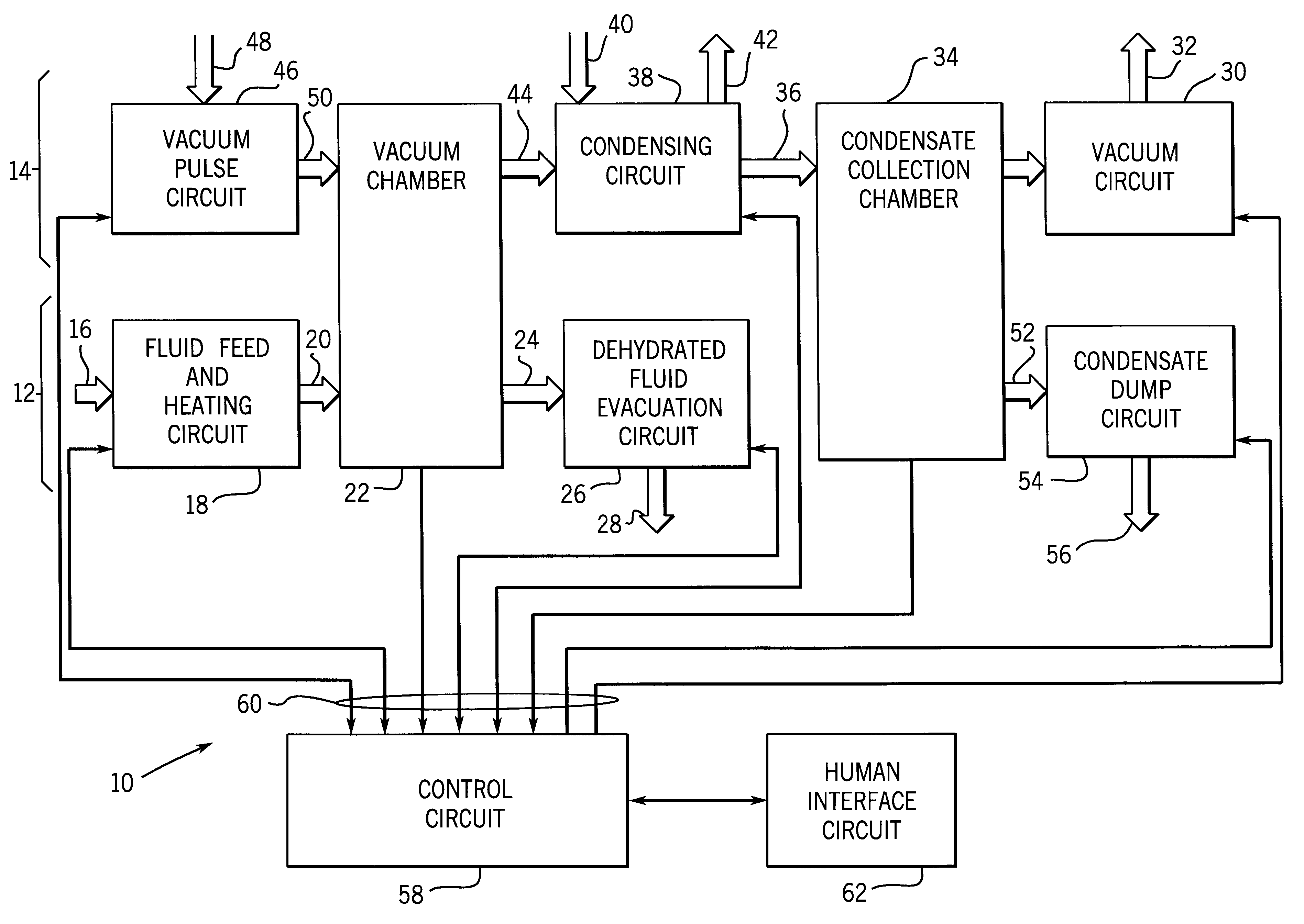
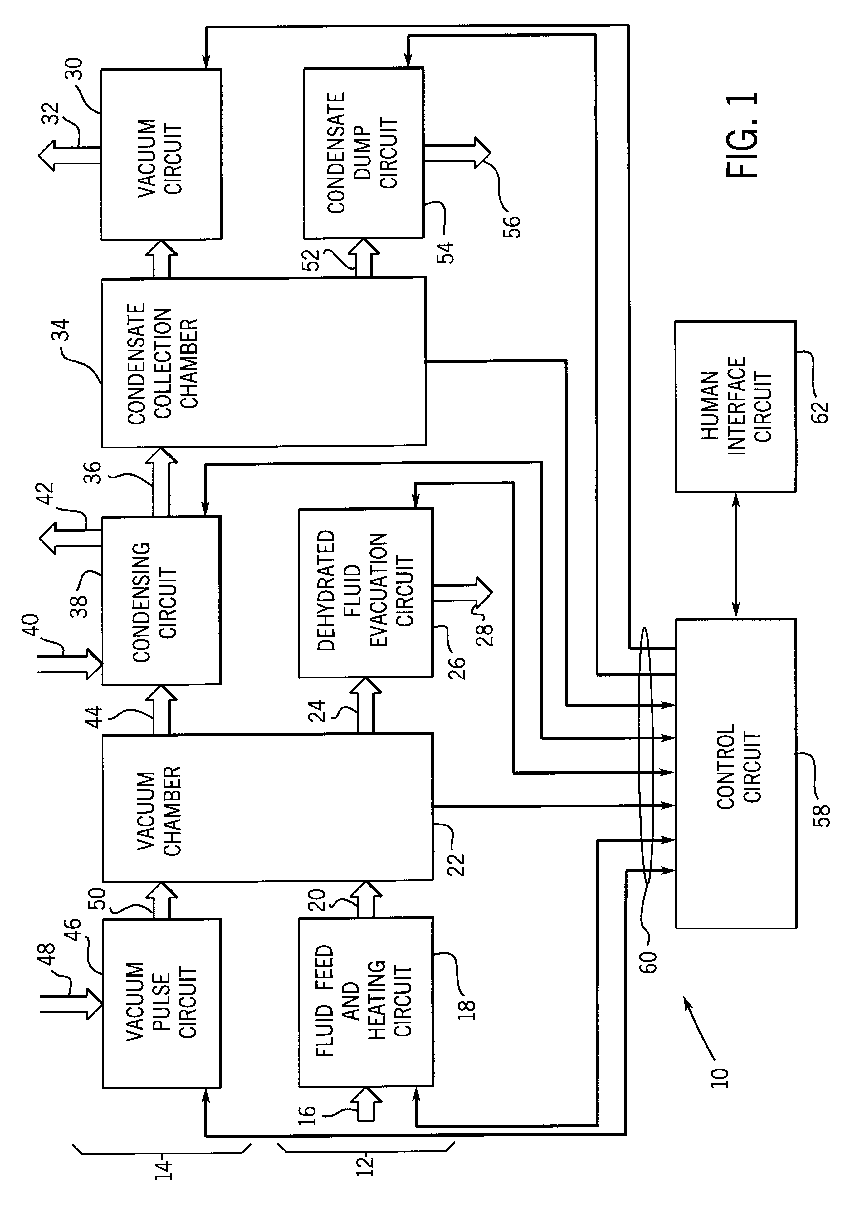
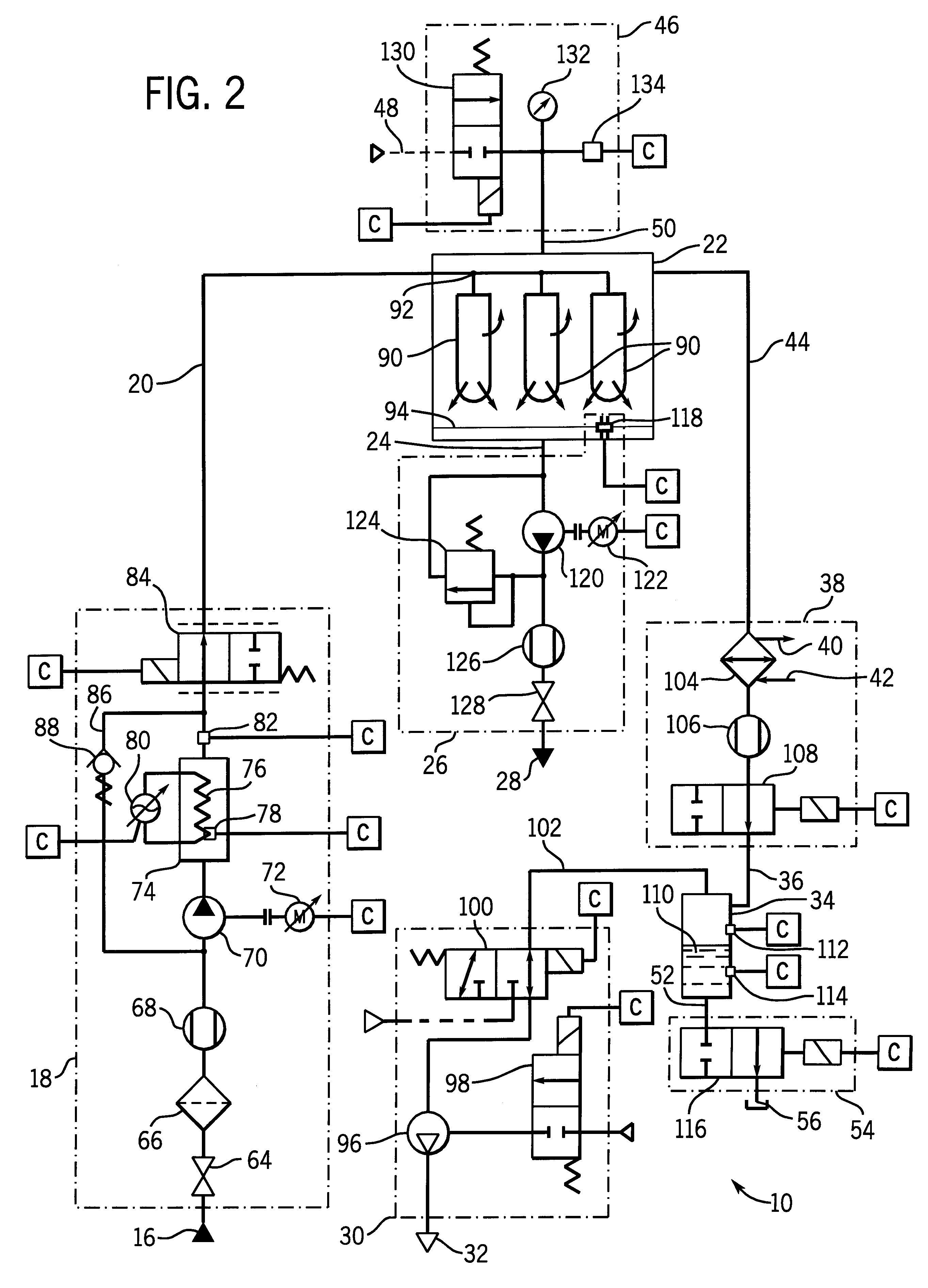
Turning now to the drawings and referring first to FIG. 1, a dehydrating system, designated generally by the reference numeral 10, is illustrated for extracting entrained and emulsified water and other contaminants from lubricating or hydraulic fluids and the like. Dehydrating system 10 generally defines a fluid flow path 12 and a gas or vacuum flow path 14 through its various components and circuits. As illustrated in FIG. 1, at an initial location in fluid flow path 12, a flow stream 16 of lubricating or hydraulic fluid is introduced into the system. Stream 16 may originate in a fluid reservoir (not shown) or directly from one or more pieces of machinery, such as gear boxes, bearing circulating systems, and so forth. Stream 16 will generally include various contaminants, such as particulate contaminants in a solid phase, as well as a liquid or gaseous phase contaminants such as emulsified water. Stream 16 enters a fluid feed and heating circuit 18 where it is pumped and heated to ...
PUM
| Property | Measurement | Unit |
|---|---|---|
| Temperature | aaaaa | aaaaa |
| Pressure | aaaaa | aaaaa |
| Flow rate | aaaaa | aaaaa |
Abstract
Description
Claims
Application Information
 - R&D
- Intellectual Property
- Life Sciences
- Materials
- Tech Scout
- Unparalleled Data Quality
- Higher Quality Content
- 60% Fewer Hallucinations
Browse by: Latest US Patents, China's latest patents, Technical Efficacy Thesaurus, Application Domain, Technology Topic, Popular Technical Reports.
© 2025 PatSnap. All rights reserved.Legal|Privacy policy|Modern Slavery Act Transparency Statement|Sitemap|About US| Contact US: help@patsnap.com


