
Method of manufacturing a film coated article

Inactive Publication Date: 2001-04-24
VISTEON GLOBAL TECH INC
View PDF61 Cites 26 Cited by
  • Summary
  • Abstract
  • Description
  • Claims
  • Application Information

AI Technical Summary

Benefits of technology

The invention enables a single operator to both load and unload a mold press from a single location. The robotically controlled loader enables the use of thin flexible films that are not rigid or self-supporting to be accurately positioned within a cavity. Accurately positioning these thin films within the cavity is critical to manufacturing a film-coated article without flaws. By enabling the use of thin films, the invention produces large molded articles that are lighter and lower cost than articles produced with rigid or self-supporting films.

Problems solved by technology

These surfaces are not always accessible, especially when molding larger parts as commonly used in the automotive industry.
A difficulty arises when attempting to automate the process of transferring the film into the mold because the film is flexible and may be damage by folding or scuffing in robotic equipment that manipulates the film.
A problem arises in handling this film after it has been thermoformed into the shape of the finished article.
The decorative surface is easily damaged because it is not rigid or self-supporting.
If the film is not properly transferred to the molding press, it may be either damaged or display a wrinkled appearance after molding.
Properly positioning the film in the mold has been a significant impediment to the wide spread use of film transfers in large-molding applications.
Conventional mold presses are encapsulated in closed off areas and are not accessible to the equipment operator.

Method used


Image

  • Method of manufacturing a film coated article
  • Method of manufacturing a film coated article
  • Method of manufacturing a film coated article

Examples


Embodiment Construction

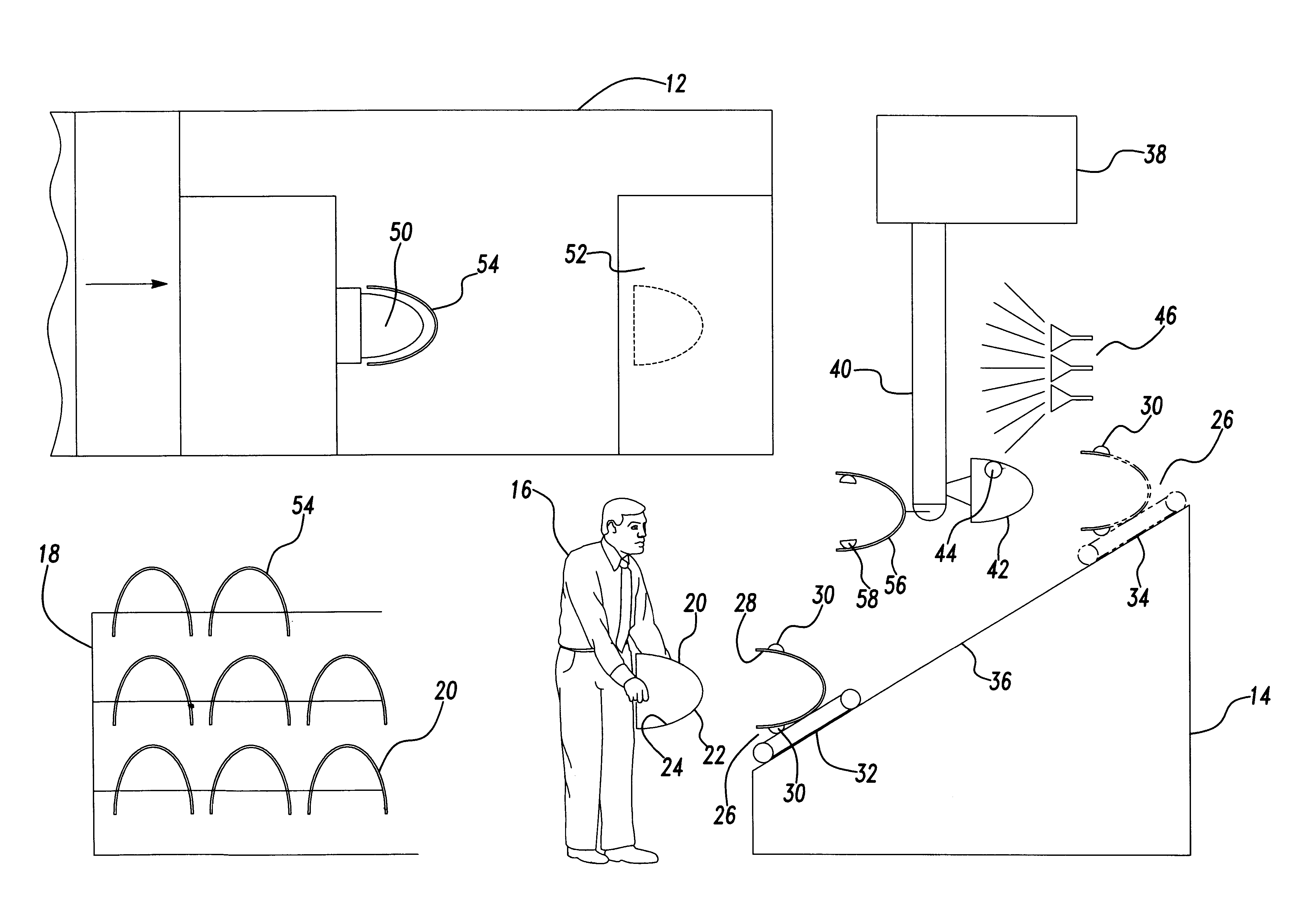
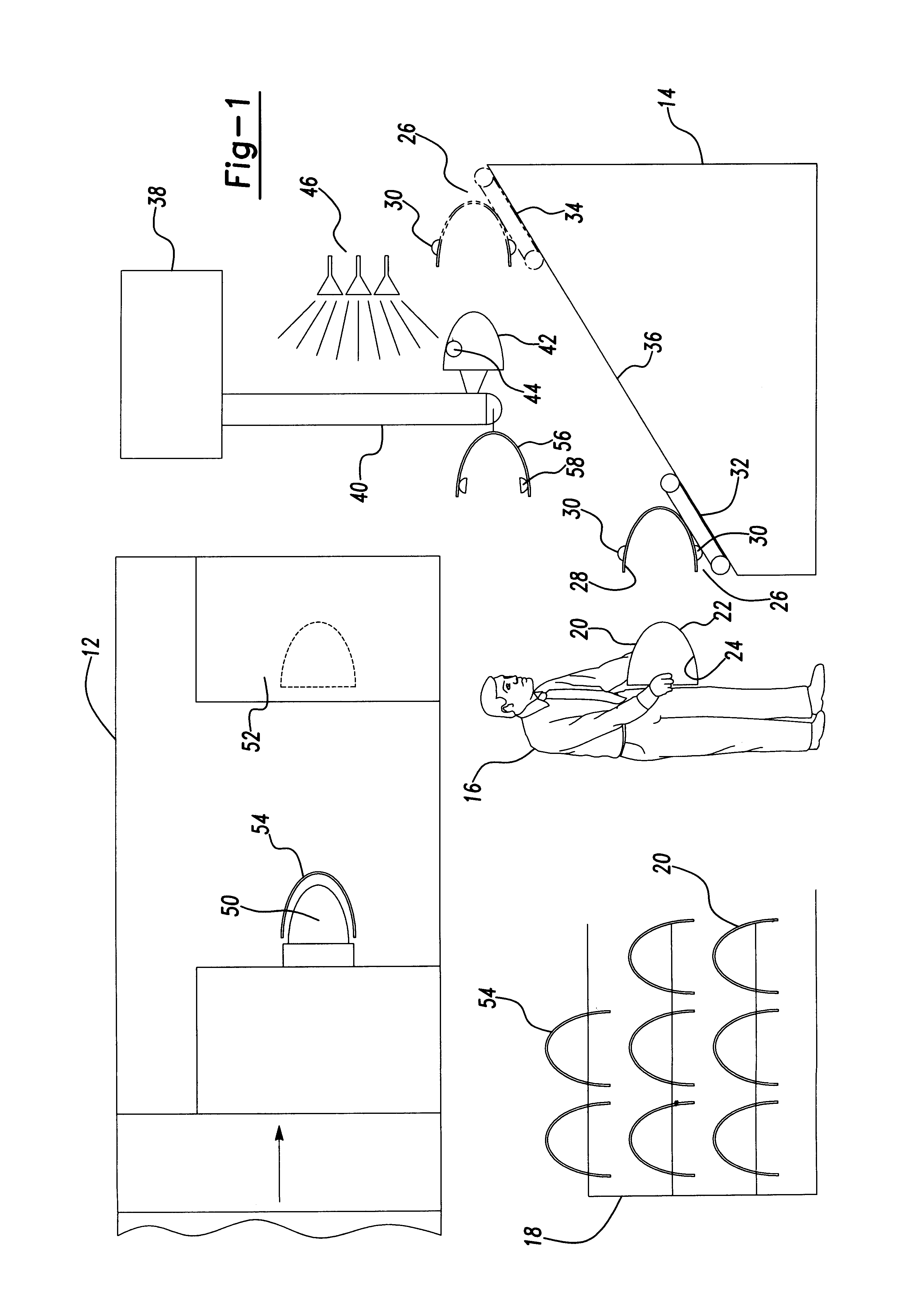
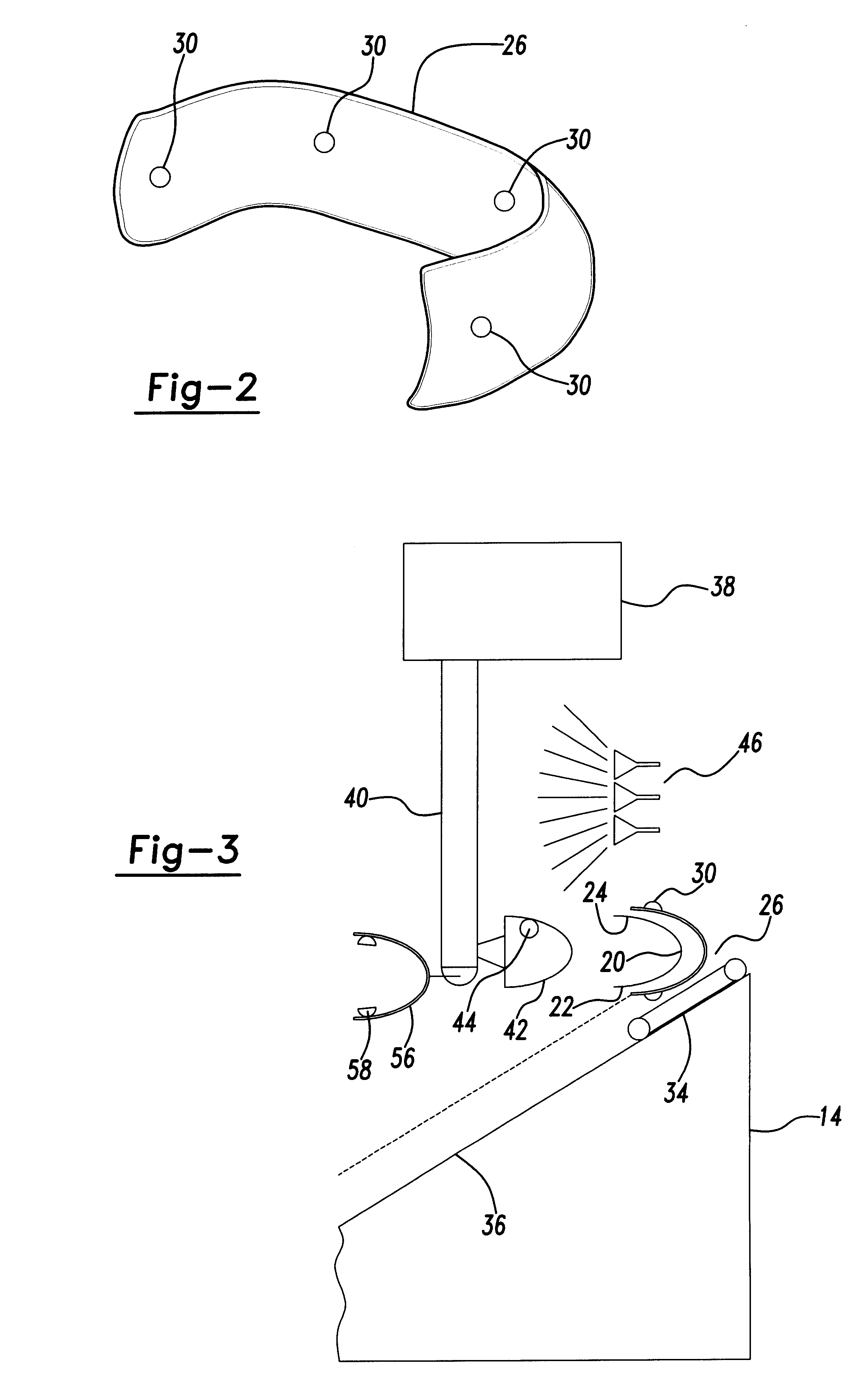
The present invention will be described through a series of drawings, which illustrates a molding operation that molds a thin film into an automotive fascia. Other components may be manufactured using the same or similar technique and equipment and are included within the invention described herein.

FIG. 1 illustrates a side view of a film transfer molding area 10. The area 10 includes a horizontal molding press 12, which is of a generally commercially available construction and design and is commonly used for manufacturing large automotive components such as fascias. Positioned adjacent the molding press 12, is an inclined transfer station 14. An operator 16 loads the film into the transfer station and receives finished molded articles. A rack 18 provides a supply of transfer films and receives the finished molded article.

As will be more fully described below, the operator 16 places a pre-molded film 20 into the transfer station 14. The pre-molded film 20 is made from a flat sheet u...


PUM

PropertyMeasurementUnit
Flexibilityaaaaaaaaaa
Vacuumaaaaaaaaaa

Abstract

A method and apparatus for manufacturing a film coated article by placing a pre-molded film into a loading station. The film has a decorative surface and a backing surface. The decorative surface is positioned juxtaposed the loading station. The film is transferred to a loader. The loader is positioned juxtaposed the backing surface. The loader and film are positioned in an open mold press between a cavity and a core. The film is transferred from the loader to the cavity. The decorative surface of the film is positioned juxtaposed the cavity. The cavity mates with the film and retains the film in position during the molding operation. The press is closed and a polymeric material is injected against the backing surface of the film. The polymeric material produces a molded article having a rigid substrate fused to the backing of the film and displaying the decorative surface. The press is opened and the molded article is transferred from the cavity to an unloader. The decorative surface of the article is positioned juxtaposed the unloader. The molded article is transferred to an unloading station and the unloader releases the molded article.

Description

BACKGROUND OF THE INVENTION1. Field of the InventionThe present invention relates to a method and apparatus for loading a pre-molded film into a mold. More specifically, the invention relates to a method and apparatus that enables the high speed loading and unloading of large automotive size components into an injection molding machine.2. Description of the Related ArtsIn-mold mold film laminates have been manufactured using movable molds and stationary cores as illustrated in U.S. Pat. No. 3,668,034('034). The '034 patent teaches placing a decorative laminate within a mold and then injection molding a polymeric material behind the laminate. The polymeric material heats, softens and finally fuses to the backing on the laminate.The finished article includes a rigid substrate of a polymeric material and an exterior surface that displays the decorative laminate. Heretofore, methods for manufacturing molded articles having this type of decorative surface have required hand placement of ...

Claims


Application Information

Patent Timeline
IPC IPC(8): B29C31/00B29C37/00B29C45/14B29C45/42B29C33/12B29C45/40B29L9/00
CPCB29C31/008B29C37/001B29C45/14008B29C45/42B29C2037/0042B29C2045/425B29L2031/3044
Inventor HARRIS, MARK ALANCHERNYAK, ZINOVIY
Owner VISTEON GLOBAL TECH INC
Learn More