
Spark plug

Inactive Publication Date: 2001-04-10
NGK SPARK PLUG CO LTD
View PDF2 Cites 15 Cited by
  • Summary
  • Abstract
  • Description
  • Claims
  • Application Information

AI Technical Summary

Benefits of technology

is to provide a spark plug capable of preventing deterioration in heat resistance, which would otherwise result from entry of high temperature combustion gas, through reduction of gas volume, as well as capable of maintaining a certain distance between the surface of the insulator and the inner wall surface of the metallic shell to thereby improve resistance to contamination with carbon for suppression of spark leak and thus to initiate regular spark discharge within an air-fuel mixture over a wide range of working conditions even when used in an engine which employs stratified charge combustion and thus tends to suffer smolder.
The inner wall surface of the metallic shell extending from the terraced portion toward the tip end of the metallic shell is tapered such that the diameter of the inner wall surface decreases toward the tip end of the metallic shell. Preferably, the amount of tapering of the inner wall surface of the metallic shell is at least 0.6 mm in terms of diameter. Through employment of this structure, gas volume decreases; accordingly, there is reduced entry into the gas volume of high temperature combustion gas generated in association with combustion of air-fuel mixture within a combustion chamber. Thus, the surface of the insulator is less exposed to high temperature combustion gas. As a result, heat resistance of the insulator is improved. Also, there can be minimized adhesion to and accumulation on the surface of the insulator of carbon generated in association with incomplete combustion of rich mixture. Further, since a certain distance is maintained between the surface of the insulator and the inner wall surface of the metallic shell securing the insulator, the adhesion and accumulation of carbon, if any, does not induce spark leak. Thus, startability of an internal combustion engine is improved, particularly in a cold season.
As described above, through reduction of a gas volume defined by the insulator and the inner wall surface of the metallic shell, there can be minimized entry of high temperature combustion gas into the gas volume during high speed operation as well as entry into the gas volume of combustion gas which contains carbon generated in association with incomplete combustion of rich mixture. Accordingly, a thermal load imposed on the insulator is decreased, and contamination with adhering carbon is prevented, thereby significantly improving heat resistance and contamination resistance and thus widening the range of operation of the spark plug.

Problems solved by technology

As a result, the leg portion of the insulator secured in the metallic shell is subjected to a very severe thermal load, potentially resulting in deterioration in heat resistance of the leg portion.
Carbon adhering to and accumulating on the insulator surface causes spark leak, which, when contamination with carbon is significant, may impair startability.
Particularly, in the case of an engine (hereinafter may be referred to as a cylinder-injection-of-fuel engine) in which fuel is directly injected into a combustion chamber, smolder tends to occur with resultant spark leak.
Moreover, since combustion temperature does not increase sufficiently, the spark plug suffers smolder due to contamination with carbon.
However, in the case of stratified charge combustion as in a cylinder-injection-of-fuel engine, spark cleaning action fails to follow the progress of contamination with carbon; consequently, contamination with carbon progresses.
Progressive contamination with carbon causes the insulating resistance (M.OMEGA.) to decrease, causing increased tendency toward flashover with resultant poor engine operation (engine stall, poor idling condition, poor drivability and defective startup).

Method used


Image

  • Spark plug
  • Spark plug
  • Spark plug

Examples


Embodiment Construction

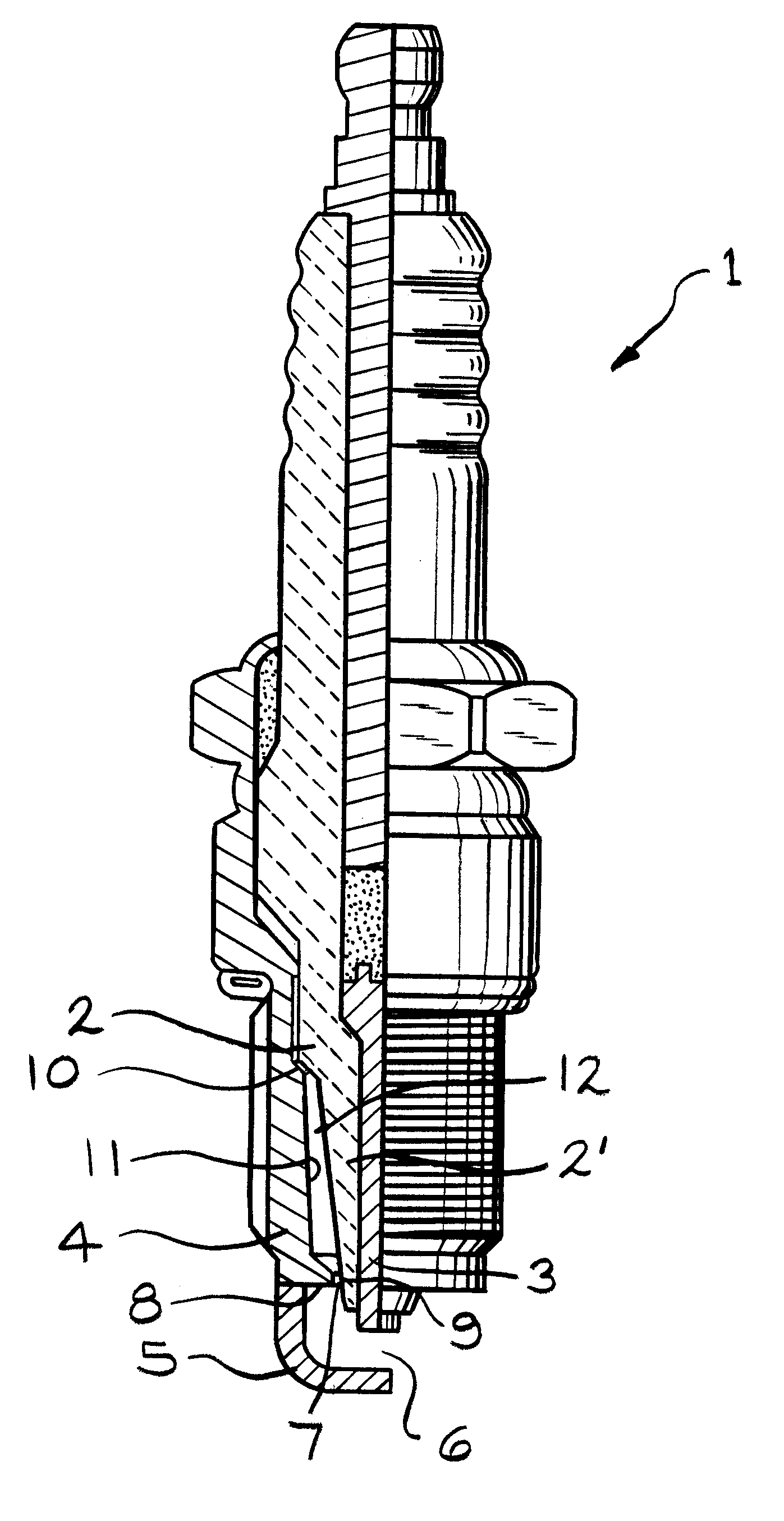
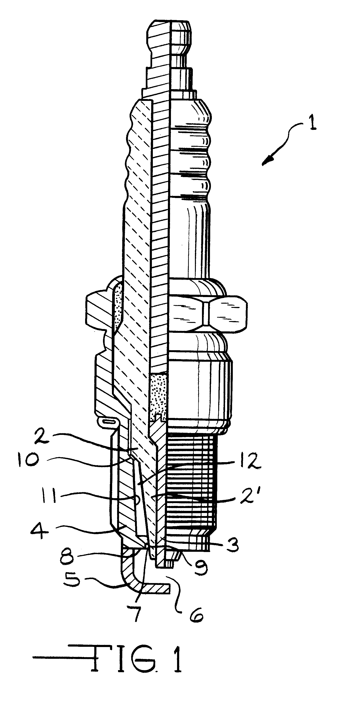
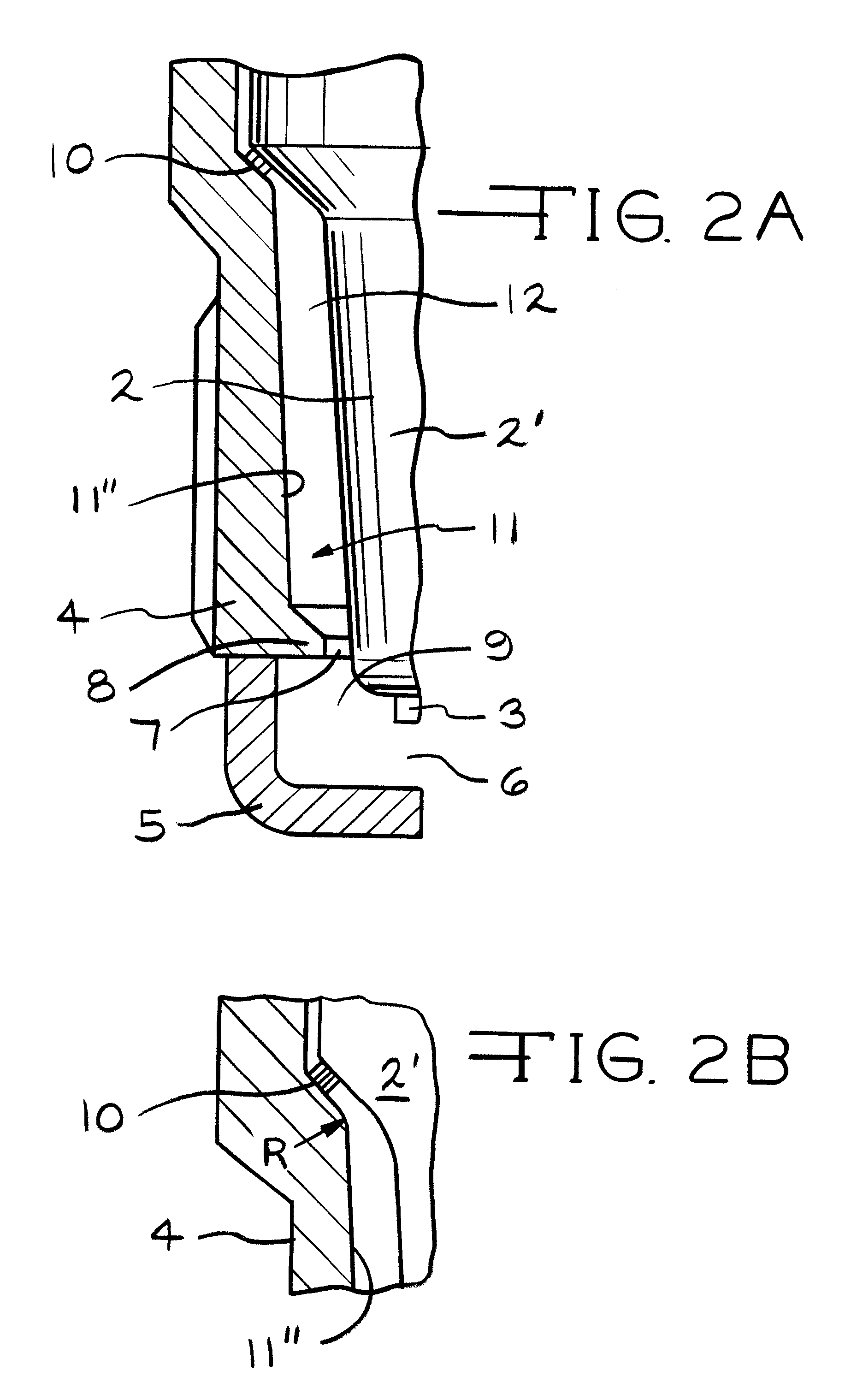
The spark plug 1 according to the first embodiment of the present invention was attached to an engine and was tested for contamination resistance and heat resistance. The effect of the invention was verified through comparison of test results with those obtained through use of a conventional spark plug (comparative example) in which the inner wall surface 11 of the metallic shell 4 is perpendicular to the open end portion 7 of the metallic shell 4. A heat resistance test was conducted through use of an 1800 cc, 4-cycle, 4-cylinder, stratified charge combustion engine. Heat resistance was evaluated in terms of the angle of advance at which preignition occurs while ignition timing (BTDC) was varied.

A contamination resistance test was also conducted through use of the same engine. The contamination resistance was evaluated in terms of an insulating resistance between electrodes as measured after 1-hour idling at a speed of 600 rpm, during which the engine is in a stratified charge comb...


PUM


Abstract

In a spark plug, a main gap is formed between the center electrode and the ground electrode, and an auxiliary gap is formed between the center electrode and a projecting inner edge formed at an open end portion of the metallic shell. The inner wall surface of the metallic shell extending from a terraced portion toward the tip end of the metallic shell is tapered such that the diameter of the inner wall surface decreases toward the tip end of the metallic shell by an amount of 0.6 mm or more. Through reduction of a gas volume defined by the insulator and the inner wall surface of the metallic shell, entry of high temperature combustion gas can be reduced to thereby decrease a thermal load imposed on the insulator, while entry of carbon can be minimized to thereby prevent contamination. Accordingly, heat resistance and contamination resistance can be significantly improved, and thus the range of operation of the spark plug can be widened.

Description

1. Field of the InventionThe present invention relates to a spark plug having an auxiliary gap in addition to a regular gap defined by a center electrode and a ground electrode in order to effectively suppress flashover which would otherwise propagate from a tip end surface of an insulator of the spark plug toward the interior of the spark plug over the surface of the insulator upon application of high voltage thereto. The present invention effectively suppresses flashover even when used in an engine which is highly likely to suffer smolder, particularly an engine designed such that during a compression stroke fuel is injected in order to form a rich mixture in the vicinity of a spark portion of a spark plug, thereby causing combustion by the spark plug (hereinafter referred to as a "stratified charge combustion engine").2. Description of the Related ArtConventionally, a certain spark plug used in an internal combustion engine has not only a main gap defined by a center electrode an...

Claims


Application Information

Patent Timeline
IPC IPC(8): H01T13/14H01T13/46H01T13/00H01T13/20
CPCH01T13/14H01T13/467
Inventor MATSUBARA, YOSHIHIRO
Owner NGK SPARK PLUG CO LTD
Learn More