
Tandem electrode welder and method of welding with two electrodes

a welder and electrode technology, applied in the field of electric arc welders, can solve the problems of extreme arc generated interference, unbalance in the three-phase power system, and limitation that was extremely detrimental,

Inactive Publication Date: 2001-03-27
LINCOLN GLOBAL INC
View PDF7 Cites 154 Cited by
  • Summary
  • Abstract
  • Description
  • Claims
  • Application Information

AI Technical Summary

Benefits of technology

The primary object of the present invention is the provision of an improved tandem electrode electric arc welder, which welder can be used for seam welding pipe from a rolled plate and similar welding operations employing pulsating high welding currents without arc interference.
Still a further object of the present invention is the provision of an improved electric arc welder, as defined above, which electric arc welder can use tandem consumable electrodes without unbalancing the power source or creating undue arc interference.

Problems solved by technology

The frequencies of the welding operation for the adjacent electrodes were the same causing extreme arc generated interference.
The prior art welders using tandem consumable electrodes had generally caused an unbalance in the three phase power system and had welding frequencies controlled by the line frequency of the input voltage.
This limitation was extremely detrimental when the high currents of pipe welding were used, which high currents exceed about 200 amperes and were often as high as about 1000-1200 amperes, or more.
When tandem mounted electrodes are subject to relatively fixed low frequencies, determined by the line frequency, and conduct extremely high currents, used in pipe welding and welding thick plates, arc interference presents a serious problem requiring complicated connections and shielding.
This procedure was extremely complicated.
The process was dictated by the line frequency and the phase shifting did not fully alleviate arc interference.
Increasing the frequency of the welding current above 100-200 Hz to reduce interference was not practical in the prior systems.

Method used


Image

  • Tandem electrode welder and method of welding with two electrodes
  • Tandem electrode welder and method of welding with two electrodes
  • Tandem electrode welder and method of welding with two electrodes

Examples


Embodiment Construction

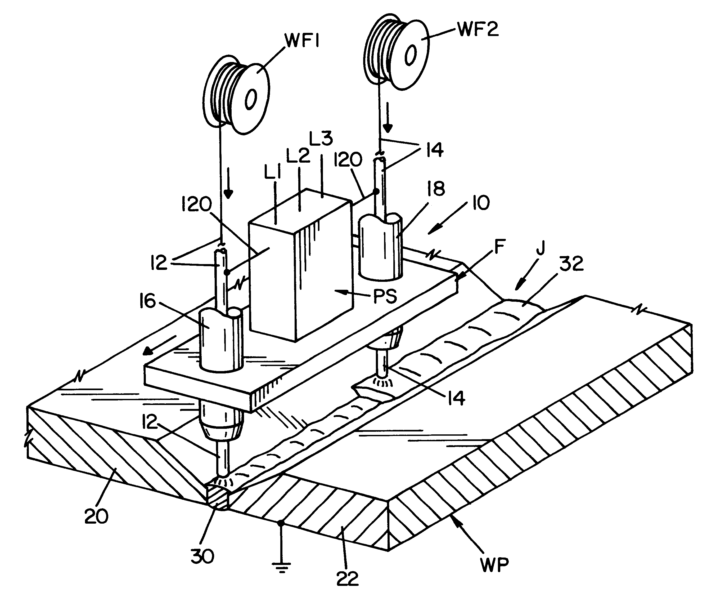
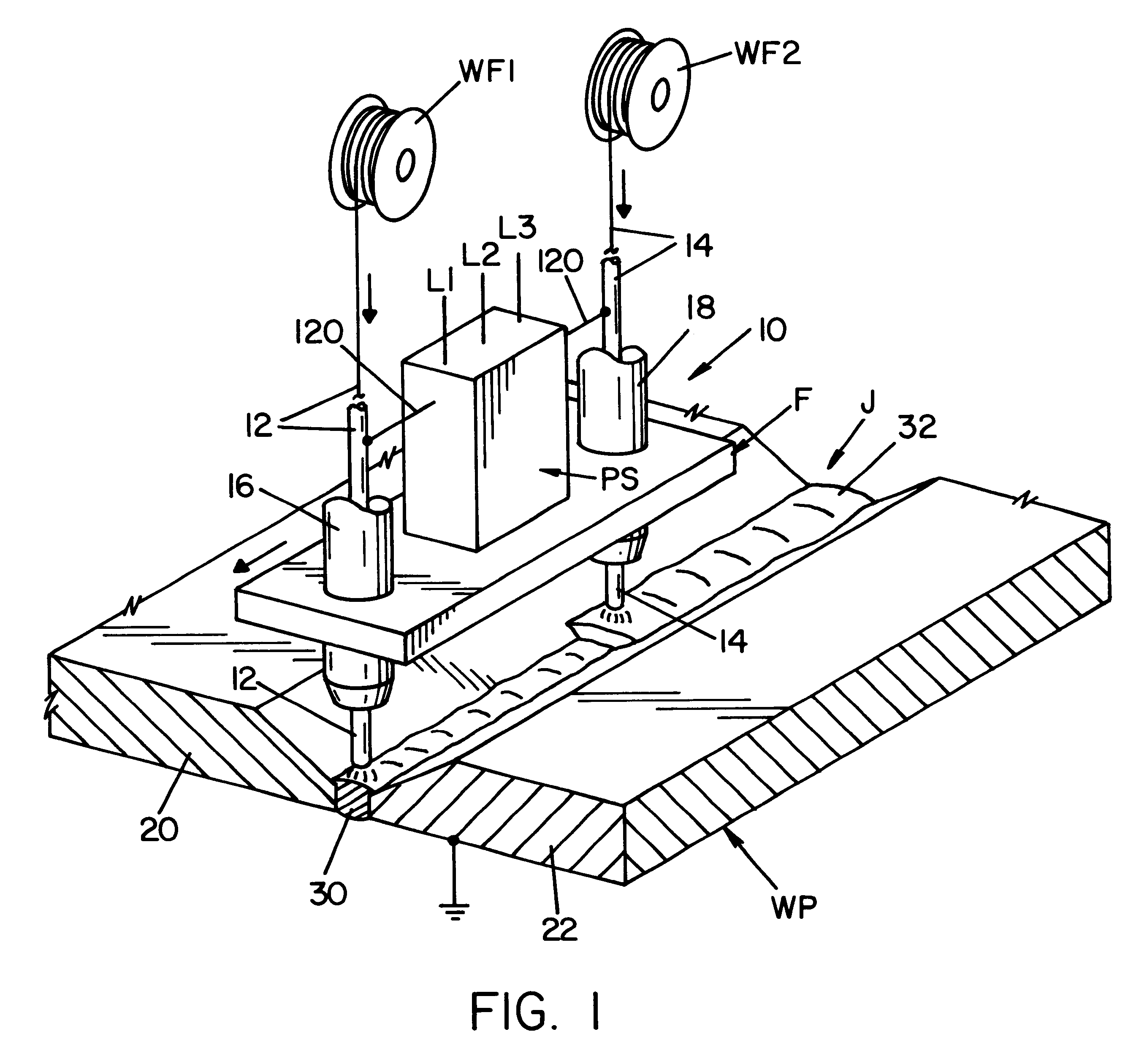
Referring now to the drawings wherein the showings are for the purpose of illustrating the preferred embodiment of the invention only, FIG. 1 shows a welder 10 including tandem mounted consumable electrodes 12, 14 in the form of welding wires advancing from supply reels WF1, WF2, respectively. Tandem electrodes 12, 14 are pushed through contact holders 16, 18 forming electrical contacts that provide pulsating, low frequency welding current between electrodes 12, 14 and spaced heavy plates 20, 22. These plates are the workpiece WP of the welding operation. Electrodes 12, 14 are moved in unison by schematically illustrated frame F to travel along a path defined by joint J between the spaced edges of plates 20, 22 to form a weld bead 30 overlaid by bead 32. The plates are joined at beads 30, 32. In the preferred embodiment, plates 20, 22 are the adjacent edges of a cylindrical pipe to weld the edges into a pipe. Frame F is transported by a tractor riding on a track to move electrodes 1...


PUM

PropertyMeasurementUnit
Currentaaaaaaaaaa
Frequencyaaaaaaaaaa
Frequencyaaaaaaaaaa

Abstract

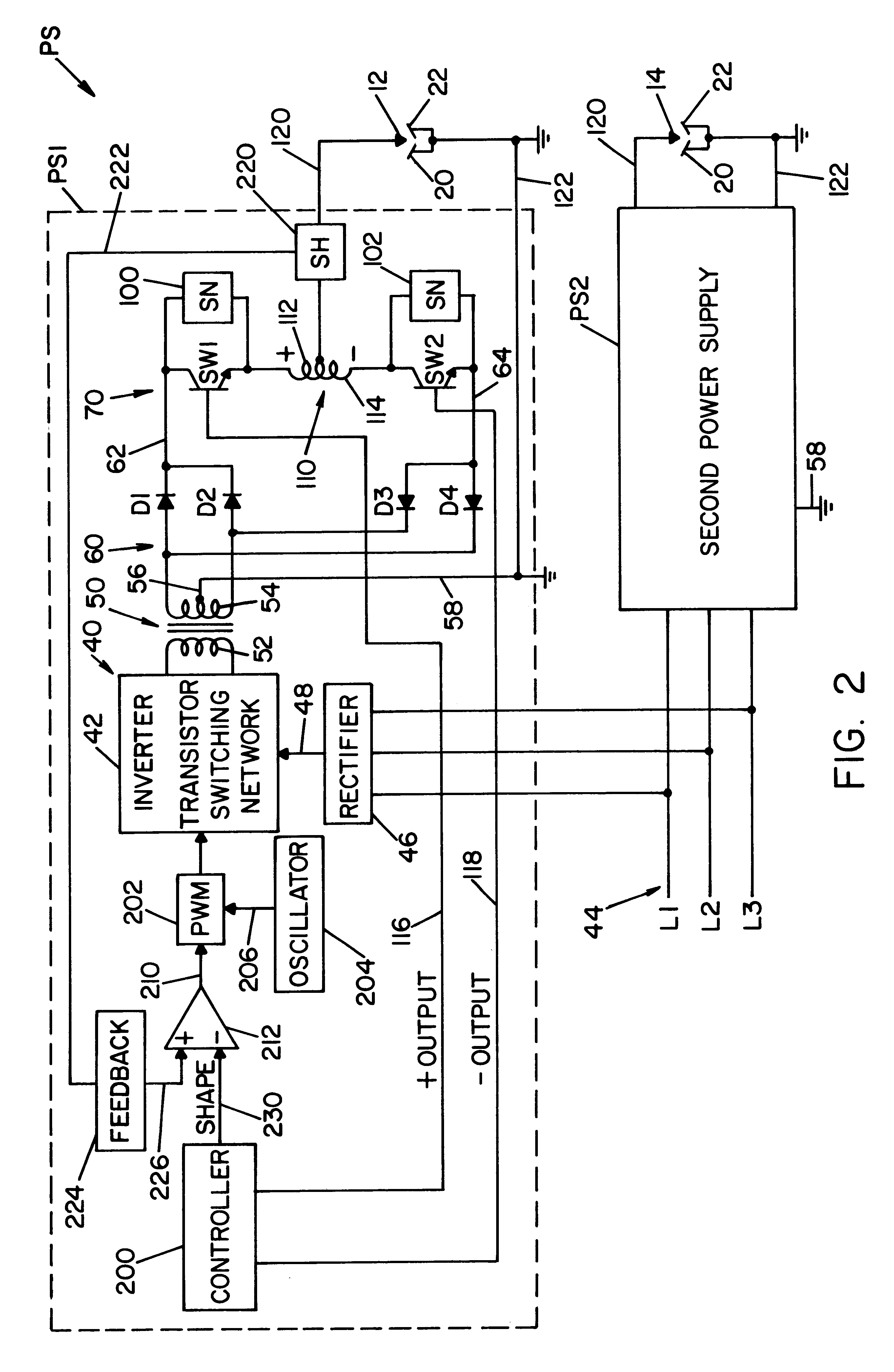
An electric arc welding apparatus comprising at least a first consumable electrode and a second consumable electrode movable in unison along a welding path between the edges of two adjacent, mutually grounded plates, a first power supply for passing a first welding current at a first low frequency between the first electrode and the two plates, a second power supply for passing a second welding current at a second low frequency between the second electrode and the two plates, where each of the power supplies includes a three phase voltage input operated at line frequency, a rectifier to convert the input voltage to a DC voltage link and a high frequency switching type inverter converting the DC voltage link to a high frequency AC current, an output rectifier circuit to provide a positive voltage tenninal and a negative voltage terminal, and an output switching network operated at a given low frequency for directing a pulsating welding current at the given low frequency from the two terminals across one of the electrodes and the plates, and a circuit for independently adjusting the given low frequency so the value of the first low frequency of the first power supply is different from the second low frequency of the second power supply.

Description

The present invention relates to the art of electric arc welding and more particularly to a welding apparatus using two consumable electrodes and the method of welding with tandem consumable electrodes.INCORPORATION BY REFERENCEThe present invention utilizes a high frequency inverter of the transistor switching type for converting a three phase input power source to a load coupling transformer from which the AC output of the inverter may be rectified to create current flow between the electrode and workpiece of a welding operation. Such welders employ a pulse width modulator operated at over 18 kHz for controlling the magnitude of the welding current flowing through the welding operation. These inverters are well known in the art and are generally shown in Blankenship 5,349,157 and Blankenship 5,351,175, which patents are incorporated by reference herein as background information. They illustrate a three phase inverter with current controlled by a high frequency pulse width modulato...

Claims


Application Information

Patent Timeline
IPC IPC(8): B23K9/10B23K9/073B23K9/09B23K9/173H02M9/00
CPCB23K9/092B23K9/1068B23K9/121B23K9/1735
Inventor STAVA, ELLIOTT K.PETERS, STEVEN R.
Owner LINCOLN GLOBAL INC
Learn More