
Flexible tube for endoscope and method of producing the flexible tube

a flexible tube and endoscope technology, applied in the field of flexible tubes for endoscopes and methods of producing flexible tubes, can solve the problems of deterioration of optical performance and breakage of internal optical fibers

Inactive Publication Date: 2001-03-27
HOYA CORP
View PDF11 Cites 87 Cited by
  • Summary
  • Abstract
  • Description
  • Claims
  • Application Information

AI Technical Summary

Benefits of technology

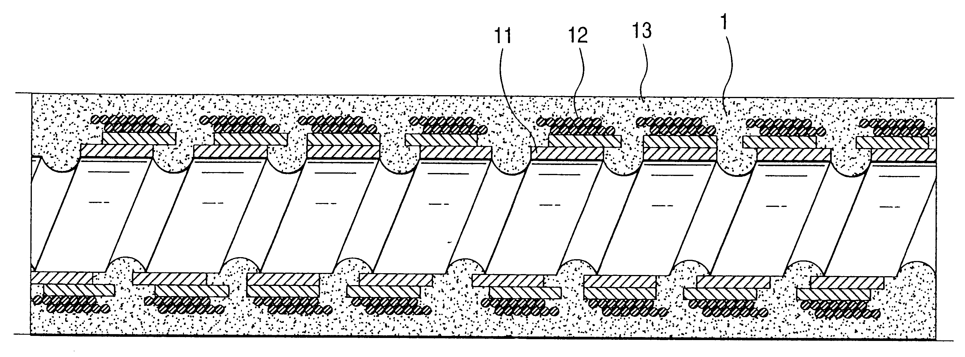
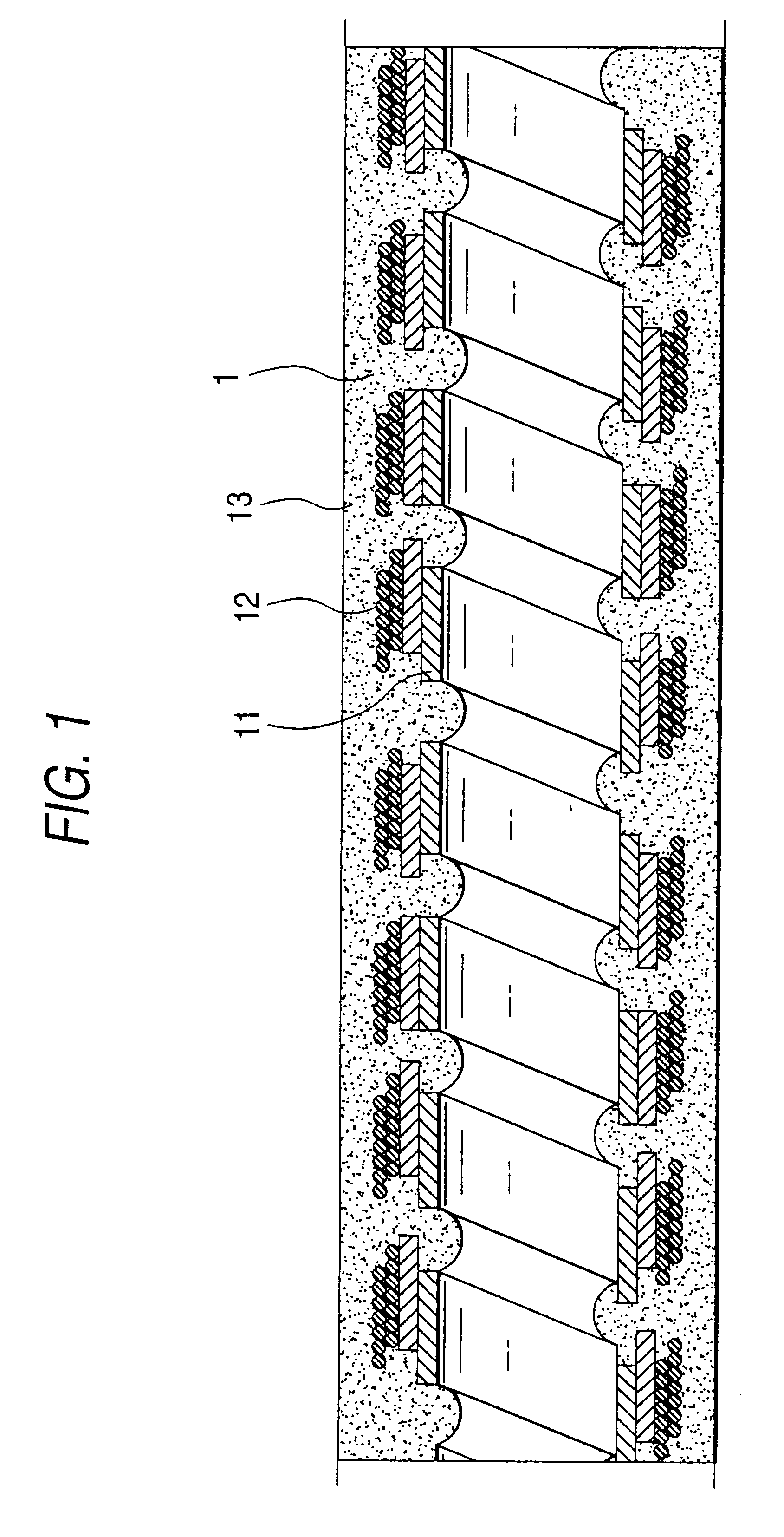
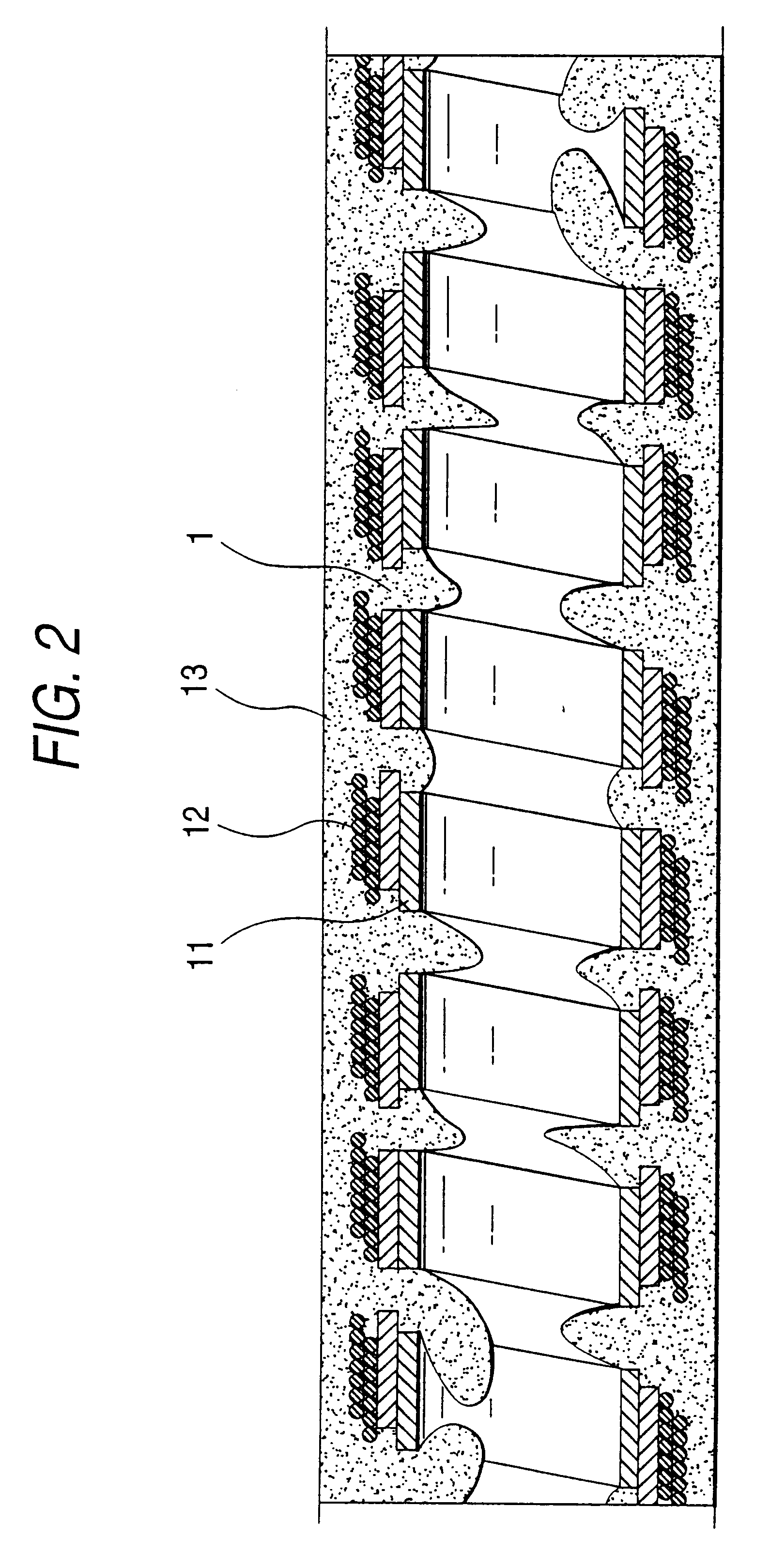
According to the present invention, the jacket material that is cured after being applied in a molten state is allowed to penetrate through gaps between adjacent layers of the spiral coil as the innermost layer until it reaches the portions of the inner surface of the spiral coil. Therefore, the inner edges of the spiral coil can be covered with the jacket material. Hence, the flexible tube for the endoscope of the present invention permits a repeat use of an endoscope without causing the internally passing optical fiber bundle and the like to be damaged by the inner surface of the innermost spiral coil. If the inner surface of the spiral coil are all or in part covered with the penetration of the jacket material, the bond between the spiral coil and other member is sufficiently enhanced to reduce the variations in flexibility that will occur after the repeat use of the endoscope.

Problems solved by technology

However, a combination between the spiral coil 11 and the reticulate tube 12 is so weak that as the result of repeat use of the endoscope, gaps form between the two members 11 and 12 and the flexible tube becomes increasingly soft to introduce difficulty in inserting the endoscope into a body cavity.
Another problem in the conventional flexible tube for the endoscope is shown in FIG. 7.
As a result, a silicone rubber tube covering a bundle of optical fibers 50 passing through the flexible tube is damaged by inner edges of the spiral coil 11, often causing the internal optical fibers to break and become deteriorated in optical performance.

Method used


Image

  • Flexible tube for endoscope and method of producing the flexible tube
  • Flexible tube for endoscope and method of producing the flexible tube
  • Flexible tube for endoscope and method of producing the flexible tube

Examples


Embodiment Construction

The present invention will now be described with reference to accompanying drawings.

FIG. 1 shows a longitudinal section of an intermediate portion of a flexible tube for an endoscope, which is typically used as a jacket for an inserting part of the endoscope or a light guide cable for connecting a light guide to a light source unit.

As an innermost layer of the flexible tube, a spiral coil 11 is used which is formed by spirally winding a strip of stainless steel or the like having a predetermined diameter, under the condition where gaps are defined between adjacent turns of the spiral coil 11. The spiral coil 11 contains two superposed layers that are wound in different directions. The spiral coil may include only one layer or three or more layers. The spiral coil has edge portions.

The spiral coil 11 is covered with a reticulate tube 12 which is formed by braiding fine stainless steel wires or the like in a tubular form. The reticulate tube 12 may also include one or more layers.

The ...


PUM


Abstract

A flexible tube for an endoscope includes a spiral coil 11 as the innermost layer and a jacket 13 that is formed by applying a melt of a jacket material 1 and then curing it, in which the jacket material 1 has been allowed to penetrate through the gaps between adjacent turns of the innermost spiral coil 11 to reach the portion of its inner surface.

Description

1. Field of the InventionThe present invention relates to a flexible tube for an endoscope used as an inserting part of an endoscope. The present invention also relates to a method of producing the flexible tube.2. Description of the Related ArtFlexible tubes for an endoscope are generally formed in such a manner that a spiral coil having one or more superposed layers are covered with a reticulate tube, which in turn is covered with a flexible jacket. The flexible jacket is formed by either of covering a flexible tube material therewith or applying a molten thermoplastic synthetic resin material on the reticulate tube and curing the applied layer.FIG. 6 shows a conventional flexible tube for the endoscope, which has a jacket 13 formed by first applying a molten thermoplastic synthetic resin material and then curing the applied layer. Obviously, a jacket material 1 has penetrated through openings in the reticulate tube 12 to bind the jacket 13 and the reticulate tube 12. A reference ...

Claims


Application Information

Patent Timeline
Patent Type & Authority Patents(United States)
IPC IPC(8): A61M25/00A61B1/005B29D23/00G02B23/24A61B1/00
CPCA61B1/00071A61B1/0011A61B1/005A61M25/0012B29D23/001G02B23/2476A61M25/005B29K2105/06B29L2023/005
Inventor OHARA, KENICHISHIBATA, YOSHINORISHIBUYA, HIROMICHIHIROSE, HITOSHIIWASAKA, KIKUOKUBOTA, TATSUOSATO, MASAYAKASAI, TADASHI
Owner HOYA CORP
Learn More