
Method for operating an electromechanical brake system

a brake system and brake technology, applied in the direction of brake systems, brake components, transportation and packaging, etc., can solve the problems of complex design of the electromechanical brake system, no longer being able to power the brake system via the on-board network,

Inactive Publication Date: 2001-03-20
CONTINENTAL AG
View PDF23 Cites 28 Cited by
  • Summary
  • Abstract
  • Description
  • Claims
  • Application Information

AI Technical Summary

Benefits of technology

, namely the creation of a reliable and exclusively electromechanical brake system (i.e., a brake system that does not contain an additional hydraulic or exclusively mechanical brake circuit).
It is accordingly an object of the present invention to be able to operate an exclusively electromechanical brake system that makes it possible to reliably decelerate and safely park a motor vehicle even if the on-board network malfunctions or fails.

Problems solved by technology

It is no longer possible to power the brake system via the on-board network if this on-board network becomes defective or fails.
However, this electromechanical brake system has a complicated design because it contains a hydraulic or mechanical brake circuit in addition to an electric brake circuit.

Method used


Image

  • Method for operating an electromechanical brake system
  • Method for operating an electromechanical brake system

Examples


first embodiment

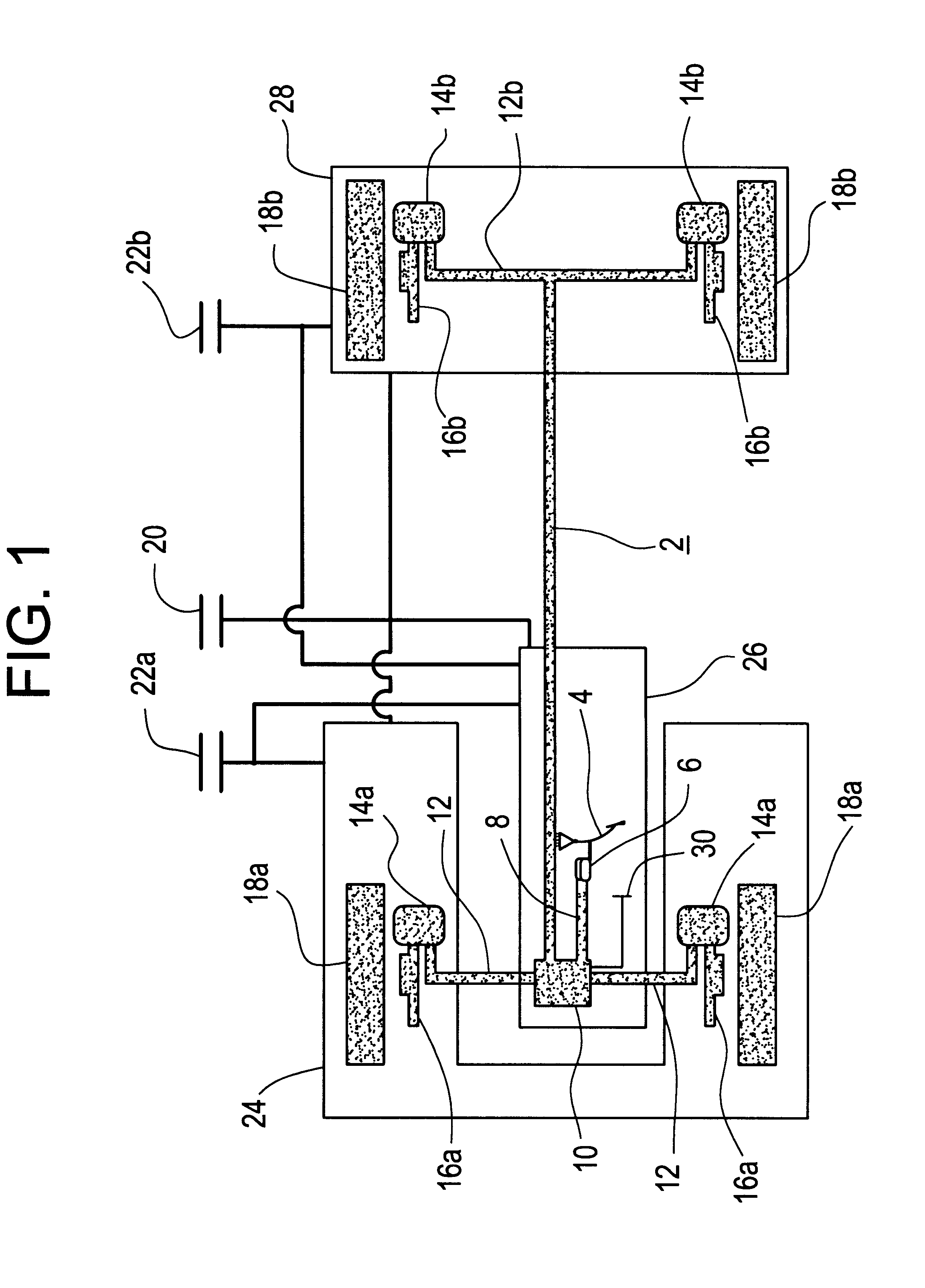
According to the invention, the power content of the emergency power storage mechanism 22b is constantly monitored by the control unit 10 in the emergency mode of the electromechanical brake system 2. If the power content of the emergency power storage mechanism 22b is above the residual power value required for locking the wheels 18b while the motor vehicle is at a standstill, the total braking force defined by the driver of the motor vehicle is divided into individual braking forces in the control unit 10, and the individual braking forces are forwarded to the respective brake actuators 14a and 14b. Corresponding clamping forces are then adjusted in the respective brake actuators 14a and 14b.

However, if the control unit 10 "determines" that the power content of the emergency power storage mechanism 22b has reached the predetermined residual power value, the control unit 10 causes the brake actuators 14b to no longer participate in decelerating the moving motor vehicle. This can be...

third embodiment

According to the invention, the second brake circuit (see box 28) is no longer operated at all in the emergency mode, i.e., this brake circuit is no longer actuated by the control unit 10. This results in the emergency power storage mechanism 22b not being used at all in the emergency mode of the electromechanical brake system 2, i.e., the power content of the emergency power storage mechanism 22b is preserved entirely. The power content of the emergency power storage mechanism 22b is then available for locking the wheels 18b with the aid of the brake actuators 14 while the motor vehicle is at a standstill. The locking of the wheels 18b in this embodiment takes place analogous to the previous description of the first embodiment.

According to a fourth embodiment of the invention, the brake system is controlled almost exactly like the third embodiment. However, once the power of the first power storage mechanism 22a is depleted (which can be monitored by the control unit 10, for exampl...


PUM


Abstract

A method is disclosed for operating an electromechanical brake system 2 of a motor vehicle that contains two brake circuits 24 and 28 that are powered by the on-board network 20 in the normal mode and by the respective emergency power storage mechanisms 22a and 22b in the emergency mode. In the emergency mode of the brake system 2, one of the two brake circuits 24, 28 is only operated by the control unit 10 until the emergency power storage mechanism 22b assigned to this brake circuit 28 has reached a residual power value that is sufficient for locking the wheels of this brake circuit at least once while the motor vehicle is at a standstill.

Description

INTRODUCTION AND BACKGROUNDThe present invention pertains to a method for operating an electromechanical brake system of a motor vehicle that contains the following components:brake actuators, one assigned to each wheel of the motor vehicle,a control unit for controlling or regulating the brake system, andtwo brake circuits that operate independently of one another and are supplied with power by an on-board network of the motor vehicle in the normal mode.Brake systems of the Brake-By-Wire type were recently developed for motor vehicles, in particular, for passenger cars. In brake systems of this type, the driver decelerates the motor vehicle by exerting a force upon the brake pedal with the foot, wherein the effect of this force exerted upon the pedal is detected by a sensor and converted into an electric signal. The signal is forwarded to individual brake actuators that are assigned to each wheel of the motor vehicle and each brake actuator exerts a braking force upon the wheel of ...

Claims


Application Information

Patent Timeline
IPC IPC(8): B60T8/88B60T8/92B60T13/74B60T13/00B60T13/66B60T8/00
CPCB60T8/885B60T2270/404
Inventor DIECKMANN, THOMAS
Owner CONTINENTAL AG
Learn More