
Fuel-reforming sheet and method of manufacture thereof

a technology of fuel-reforming devices and powdered powders, which is applied in the direction of physical/chemical process catalysts, separation processes, other chemical processes, etc., can solve the problems of time-consuming and expensive manufacturing of such fuel-reforming devices, inconvenience of having to place such fuel-reforming devices inside the fuel tank, and difficulty in neatly and uniformly dispersing powders

Inactive Publication Date: 2001-03-13
FENIC
View PDF7 Cites 8 Cited by
  • Summary
  • Abstract
  • Description
  • Claims
  • Application Information

AI Technical Summary

Benefits of technology

As described above, the present invention provides a fuel-reforming sheet which is adapted to be placed in the air flow channel of an automobile engine a heat engine to ionize the oxygen molecules in the air in order to achieve complete combustion of the oxygen mixed with the fuel, whereby the fuel-reforming sheet of the present invention makes it possible to improve the power and fuel efficiency of the heat engine, while at the same time reducing unwanted emissions in the exhaust gas.Further, by using a double-sided adhesive sheet having one side bonded to a sheet-shaped backing and another side which has powdered grains uniformly dispersed thereon, the present invention makes it possible to firmly bond the powdered grains uniformly to the sheet-shaped backing. Also, by using a flexible backing, the present invention provides a fuel-reforming sheet which is simple to install in the air flow channel of an air flow duct without the need for the type of fasteners used in prior art devices. Thus, the present invention provides a fuel-reforming sheet which is easy to use and manufacture.Moreover, because the fuel-reforming sheet according to the present invention uses powdered grains only within a prescribed size range, it is possible firmly bond the powdered grains to the backing, and this makes it possible to use the fuel-reforming sheet of the present invention over a long period of time without the risk of the powdered grains fall off the backing.Finally, it is to be understood that the present invention is not limited to the embodiments described above, and it is possible to make various changes and additions without departing from the scope and spirit of the invention as defined by the appended claims.TABLE 2TABLE 3TABLE 4TABLE 5TABLE 6TABLE 7TABLE 8TABLE 9TABLE 10TABLE 11

Problems solved by technology

However, the requirement of a baking step or the like when processing the ceramic powder and radioactive rare-earth mineral powder makes it time-consuming and expensive to manufacture such a fuel-reforming device.
Furthermore, there is the inconvenience of having to place such a fuel-reforming device inside the fuel tank.
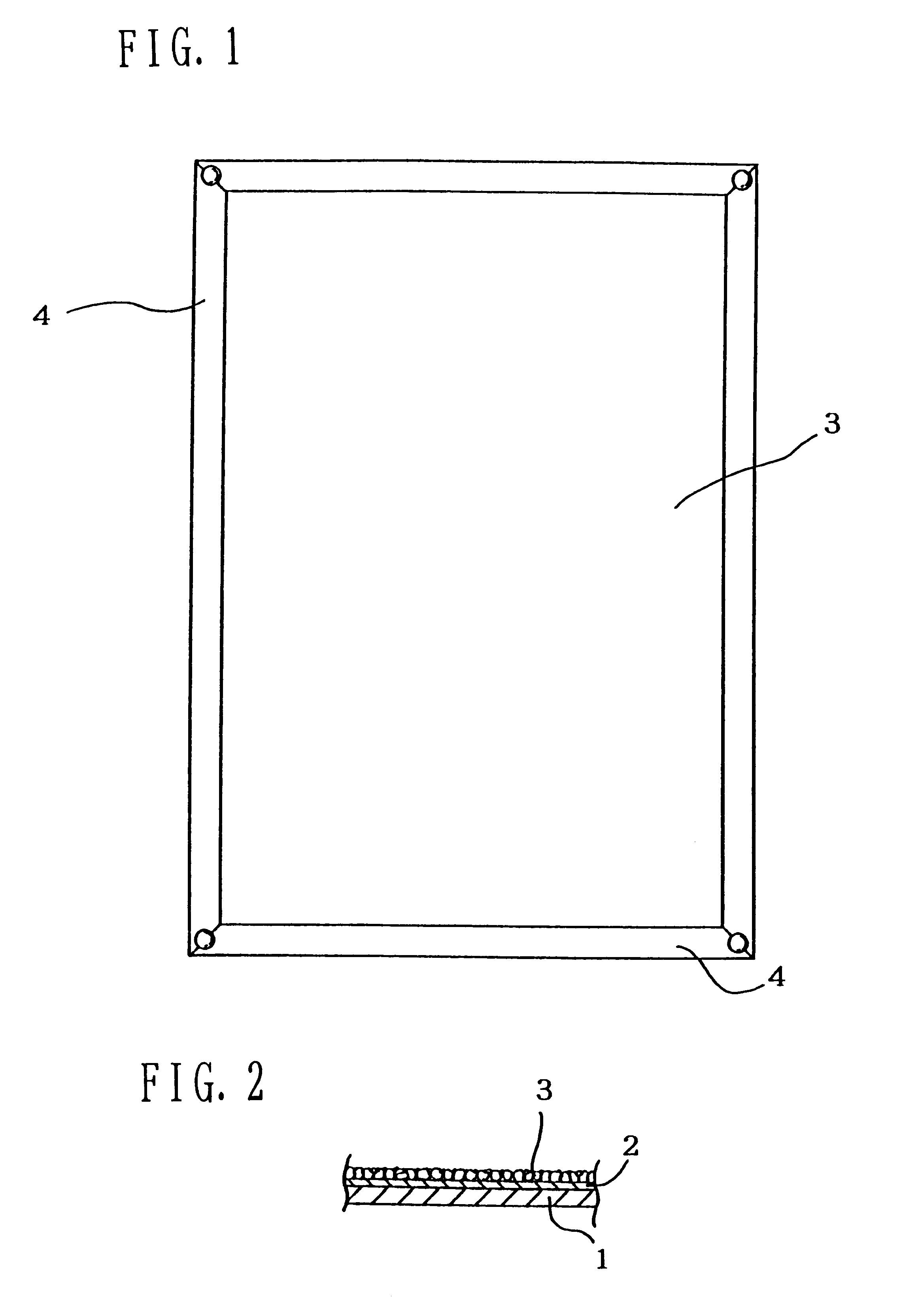
However, in the case where the adhesive is directly applied to the surface of the backing 1, it is difficult to neatly and uniformly disperse and bond the powdered mixture 3 to the adhesive surface, and such arrangement can also lead to localized uneven application.

Method used


Image

  • Fuel-reforming sheet and method of manufacture thereof
  • Fuel-reforming sheet and method of manufacture thereof
  • Fuel-reforming sheet and method of manufacture thereof

Examples


specific embodiment 2

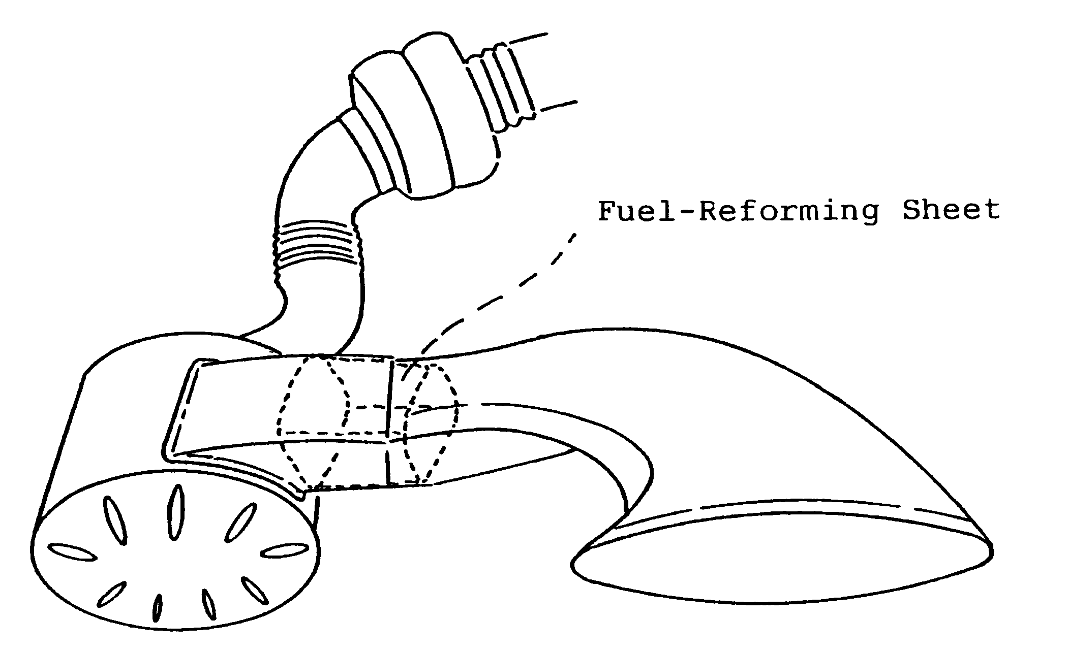
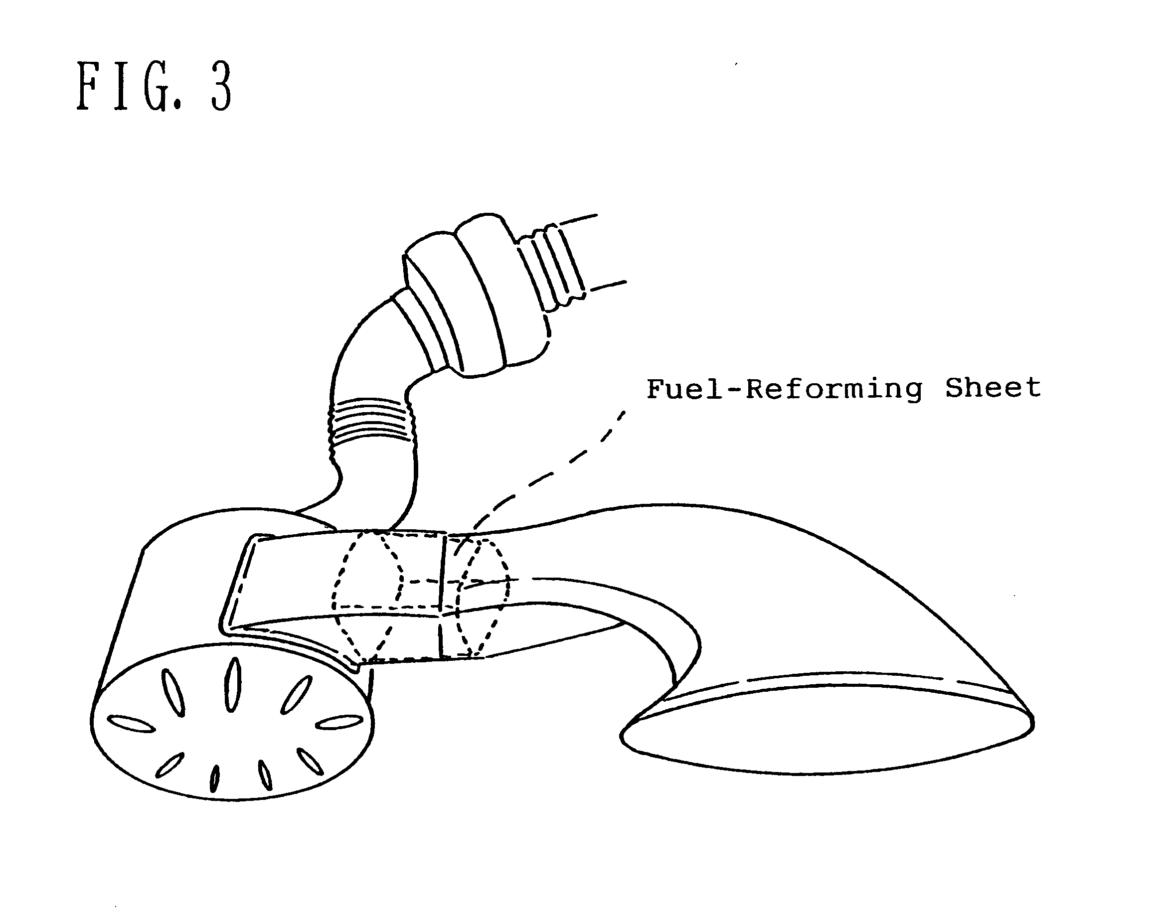
A fuel-reforming sheet constructed as described above was placed inside the air flow channel of an automobile in between the air intake port and the air filter at a position near the air filter. A Nissan Bluebird Model E-PC910 was used for the automobile, L.P.G. was used as a fuel (which is the fuel used by private taxis in Japan), and the driving range was inside the Japanese city of Kitakyushu (with the air conditioner in use). Tables 3 and 4 show results such as the driving distance per liter of fuel and the fuel efficiency for both before and after installation of the fuel-reforming sheet.

TABLE 3

TABLE 4

specific embodiment 3

A fuel-reforming sheet constructed as described above was placed inside the air flow channel of an automobile in between the air intake port and the air filter at a position near the air filter. A Toyota Corolla Model E-AE91 was used for the automobile, gasoline was used as a fuel, and the driving range was between the Kurume Interchange and the Kumamoto Interchange in Japan (with the air conditioner in use). Tables 5 and 6 show results such as the driving distance per liter of fuel and the fuel efficiency for both before and after installation of the fuel-reforming sheet.

TABLE 5

TABLE 6

specific embodiment 4

A fuel-reforming sheet constructed as described above was placed inside the air flow channel of an automobile in between the air intake port and the air filter at a position near the air filter. A Toyota Corolla Model E-AE91 was used for the automobile, gasoline was used as a fuel, and the driving range was between the Kurume Interchange and the Kumamoto Interchange in Japan (with the air conditioner in use). Tables 7 and 8 show results such as the driving distance per liter of fuel and the fuel efficiency for both before and after installation of the fuel-reforming sheet.

TABLE 7

TABLE 8


PUM

PropertyMeasurementUnit
porosityaaaaaaaaaa
porosityaaaaaaaaaa
widthaaaaaaaaaa

Abstract

A fuel-reforming sheet which is adapted to be placed in the air flow channel of a heat engine to ionize the oxygen molecules in order to achieve complete combustion of the oxygen mixed with a fuel is constructed from a flexible backing, a double-sided adhesive sheet having front and back adhesive surfaces, and a powdered mixture which includes a ceramic powder, a radioactive rare-earth mineral powder and a binder, in which the rear adhesive surface of the double-sided adhesive sheet is bonded to the flexible backing and the powdered mixture is bonded to the front adhesive surface of the double-sided adhesive sheet.

Description

1. Field of the InventionThe present invention relates to a fuel-reforming sheet and method of manufacture thereof for improving the fuel efficiencies of various types of heat engines, such as those used in work trucks, buses, passenger cars, marine vessels and boilers, which use liquid fuels such as gasoline, light fuel oil, heavy fuel oil and methanol, and gas fuels such as LPG and natural gas, while at the same time making it possible to drastically reduce emissions such as CO, HC and black smoke (produced by Diesel engines) in the exhaust gas of such heat engines.2. Description of the Prior ArtIn the field of fuel-reforming devices, the present inventor previously invented a fuel-reforming device (disclosed in Japanese Utility Model Application No. HEI 8-10566) in which a ceramic powder and a radioactive rare-earth mineral powder were mixed, granulated, dried, baked, grounded to form spherically shaped grains having roughly the same diameter, and filled into a cylindrical body w...

Claims


Application Information

Patent Timeline
Patent Type & Authority Patents(United States)
IPC IPC(8): F02M27/00F02M27/04F02M27/06C09K3/00F02M27/02
CPCF02M27/04F02M27/065
Inventor WATANABE, TAKASHINOGAMI, HIDEAKI
Owner FENIC
Learn More