
Infrared fiber imager

a fiber imager and infrared technology, applied in the field of infrared fiber imagers, can solve the problems of affecting tissue application, impractical use of fiber bundles,

Inactive Publication Date: 2001-01-16
THE UNITED STATES OF AMERICA AS REPRESENTED BY THE SECRETARY OF THE NAVY
View PDF2 Cites 28 Cited by
  • Summary
  • Abstract
  • Description
  • Claims
  • Application Information

AI Technical Summary

Problems solved by technology

Its application to tissues has been hampered by problems in sample preparation for optimal spectra acquisition and the strong absorption of infrared light by water.
Other problems of the prior art generally relate to the large size of fibers employer which made the use of a fiber bundle impractical for remote in-vivo biomedical imaging.

Method used


Image

  • Infrared fiber imager
  • Infrared fiber imager
  • Infrared fiber imager

Examples


example 1

This example demonstrates transmission of light through a chalcogenide fiber bundle.

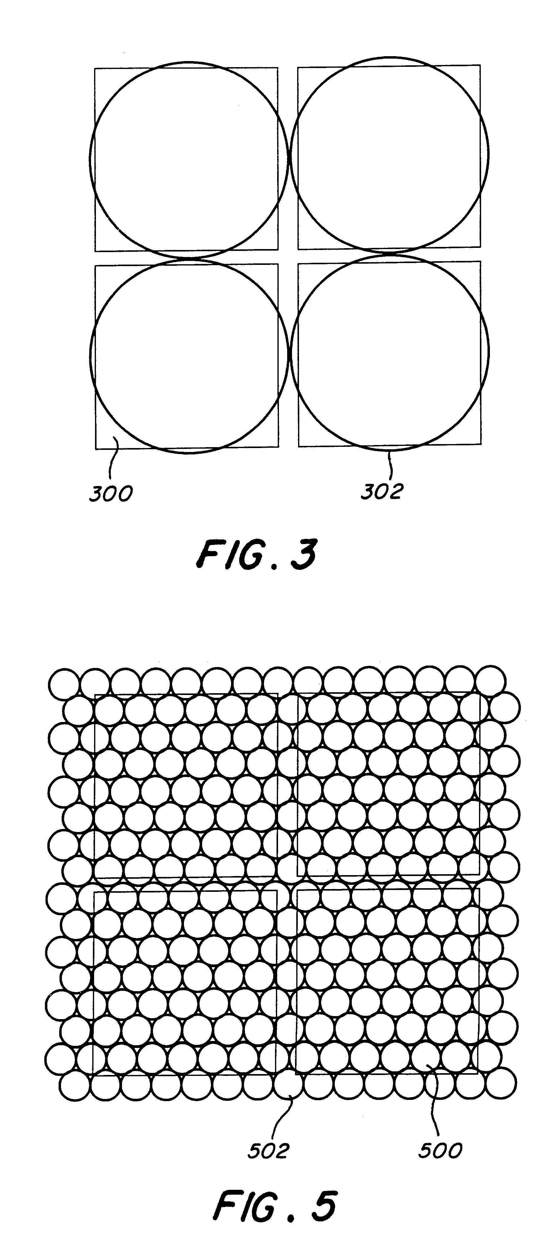
Pursuant to objectives of this example, 100 As.sub.40 S.sub.60 glass fibers were formed into a coherent bundle where the fibers were in a hexagonal pack arrangement that was generally circular in cross-section. The fibers were 35 microns in outside diameter, which included Teflon polymer cladding 5 microns in thickness. The fibers were disposed in a sheath and the bundle was circular in cross-section.

The fiber bundle was illuminated at one end with a CW CO laser operating at 5.4 microns under about 4 watts of incident power and the image shown in FIG. 7 was recorded at the other end of the bundle with a Spiricon camera operating at wavelength of 3-5 microns.


PUM


Abstract

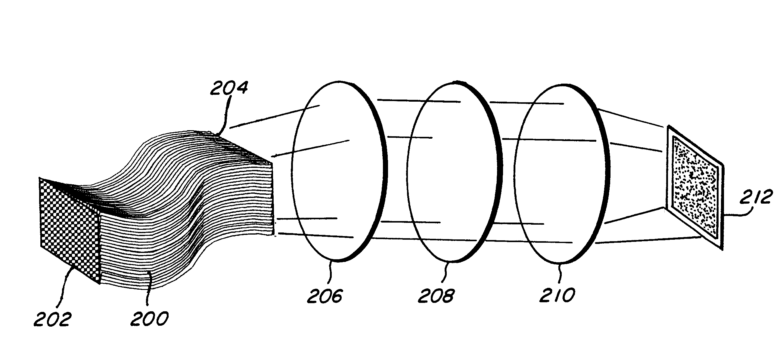
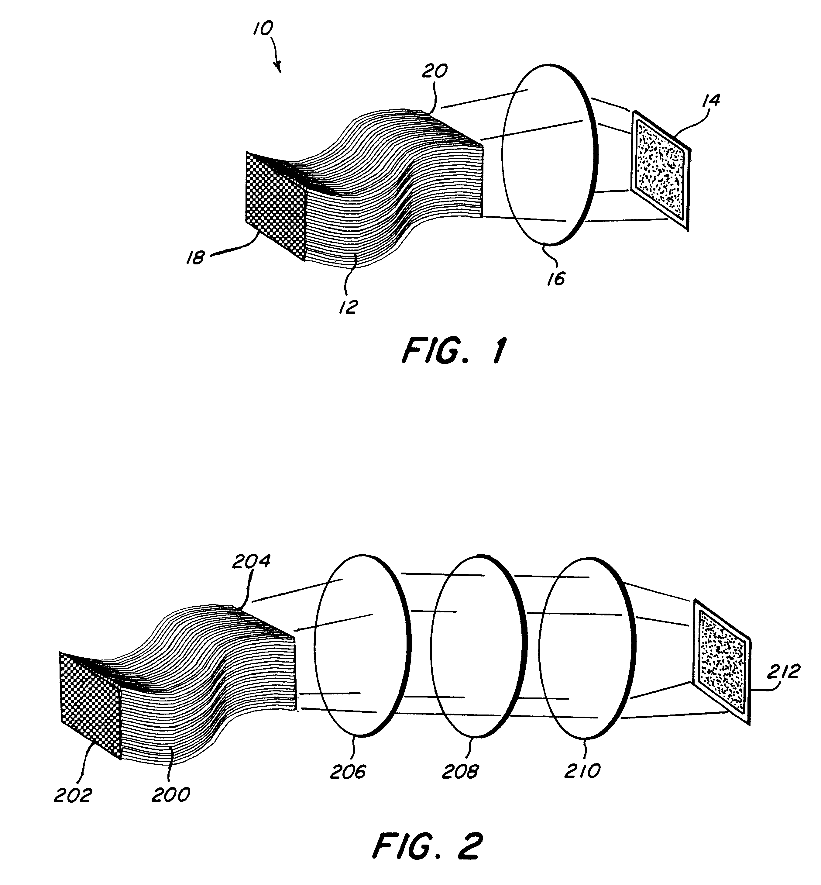
An apparatus for performing spatial and spectral analysis comprising a bundle of a plurality of chalcogenide glass fiber, an optical system for transmitting light received from the bundle, and a detector for receiving the light signal from the optical system for providing spatial and spectral analysis of the bundle image; maximum diameter of the fibers is about the size of the pixels on the detector.

Description

Field of the InventionThis invention pertains to an apparatus characterized by a bundle of chalcogenide fibers coupled to a detector.Description of Related Prior ArtInfrared spectroscopy is a powerful procedure for the study of not only chemical compounds but also their relationship to surrounding molecules. Its application to tissues has been hampered by problems in sample preparation for optimal spectra acquisition and the strong absorption of infrared light by water. By resolving technical and methodological problems, it is possible to apply infrared spectroscopy to the study of human and other tissues. Thus, it is possible to demonstrate that the spectra of cancerous flesh tissues are significantly different from those of corresponding non-cancerous tissues.Other problems of the prior art generally relate to the large size of fibers employer which made the use of a fiber bundle impractical for remote in-vivo biomedical imaging.The article entitled "Recent Advances And Trends in ...

Claims


Application Information

Patent Timeline
IPC IPC(8): G02B6/06G02B6/02
CPCG02B6/06G02B6/02
Inventor SANGHERA, JASBINDERAGGARWAL, ISHWAR D.SHAW, BRANDONPUREZA, PAUL
Owner THE UNITED STATES OF AMERICA AS REPRESENTED BY THE SECRETARY OF THE NAVY
Learn More