Coding mode determination system

a technology of coding mode and determination system, which is applied in the direction of code conversion, instruments, computing, etc., can solve the problem of maximization of coding efficiency

Inactive Publication Date: 2000-10-31
KDDI CORP
View PDF5 Cites 18 Cited by
  • Summary
  • Abstract
  • Description
  • Claims
  • Application Information

AI Technical Summary

Benefits of technology

In accordance with the present invention, first, macro-blocks of an inter-frame predictive difference picture and of an intra-frame picture are divided into sub-blocks, and the dispersion values in the inside of them are calculated, respectively. Then, they are transformed to estimated amounts of generated encoded information by a nonlinear function for estimating an amount of generated encoded information from a dispersion value. Further, the values are added together in the macro-blocks to calculate the estimated amounts of generated encoded information in the macro-blocks. The comparison of them between the inter-frame predictive difference picture and the intra-frame picture enables mode determination to be performed by the magnitude of the estimated amount of generated encoded information, and a determination can be achieved which is more appropriate in the sense of coding efficiency.

Problems solved by technology

The amount of generated encoded information in coding is important for encoding efficiency, but the conventional dispersion compare in a macro-block does not always correspond to whether such amount is large or small, and thus there is a problem that it is not always an optimum determination method in the sense of mode determination that the coding efficiency is maximized.

Method used


Image

  • Coding mode determination system
  • Coding mode determination system
  • Coding mode determination system

Examples


second embodiment

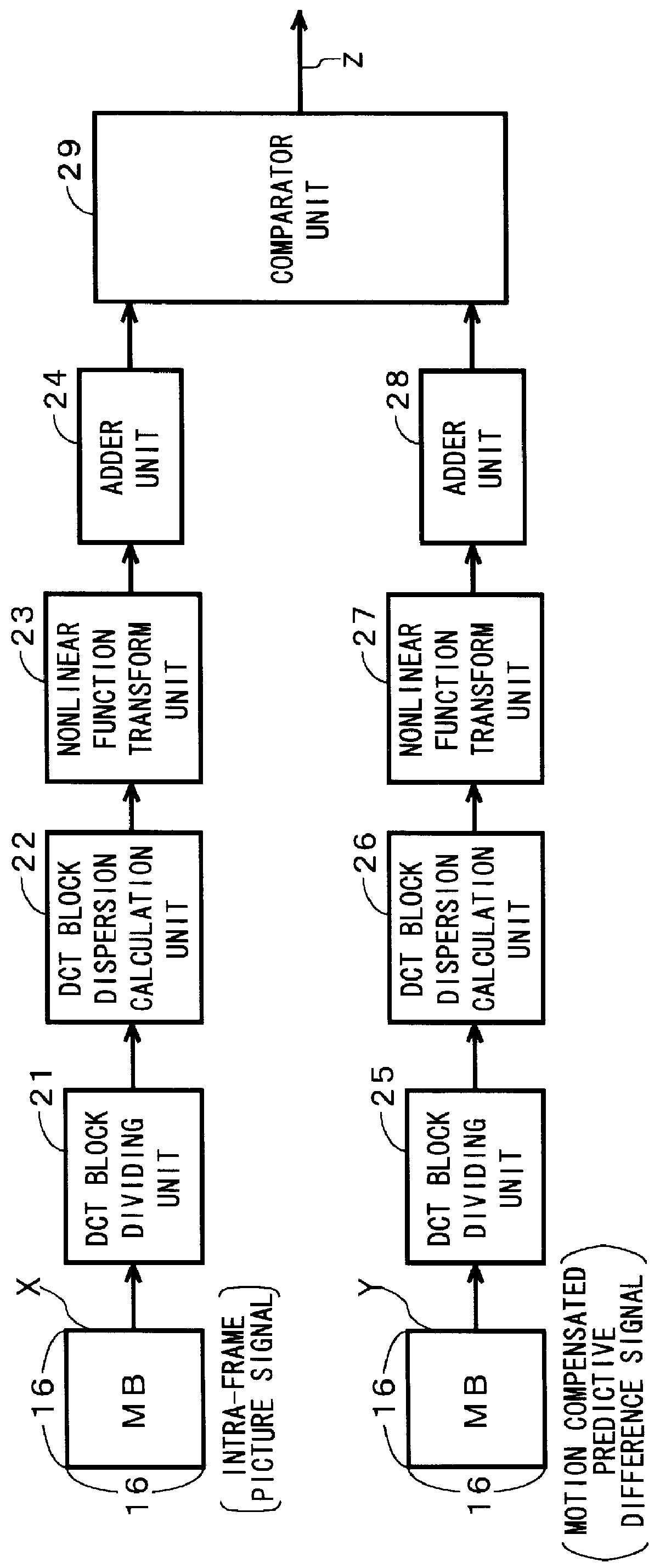
the present invention is described below. In this embodiment, the estimation of the amount of generated encoded information is performed more accurately by utilizing the fact that the dispersion of the intra-frame picture signal X can be approximated by the uniform distribution and the dispersion of the predictive difference signal Y can be approximated by the Laplace distribution. That is, the following equation (2) is used in the nonlinear function transform unit 23 in FIG. 2, and the following equation (10) is used in the nonlinear function transform unit 27.

I(x)=log.sub.2 1 2.sigma.j.sup.2 (9)

I(x)=log.sub.2 2e.sup.2 .sigma.j.sup.2 (10)

Although the present invention has been specifically described in the above embodiments, the present invention is not limited to this, but it is obvious that modifications made to the extent that they do not depart from the spirit of the present invention are included in the present invention.

As described above, in accordance with the present inven...


PUM


Abstract

This invention provides a mode determination system for maximizing the coding efficiency by minimizing the amount of generated encoded information. An intra-frame picture signal X of 16 pels 16 lines is divided into four sub-blocks of 8 pelsx8 lines by a DCT block dividing unit. A DCT block dispersion calculation unit calculates the dispersions of the four sub-blocks, and a nonlinear function transform unit transforms the dispersions to values for estimating amounts of generated encoded information. An adder unit adds together the four values for estimating amounts of generated encoded information and outputs the sum. On the other hand, a motion compensated predictive difference Y of 16 pelsx16 lines undergoes a processing similar to said intra-frame picture signal X by a DCT block dividing unit, a DCT block dispersion calculation unit, a nonlinear function transform unit and an adder unit, and a value for estimating an amount of generated encoded information for the motion compensated predictive difference Y is outputted from the adder unit. An comparator unit outputs a signal for selecting a mode according to which of the two values for estimating amounts of generated encoded information is smaller.

Description

1. Field of the InventionThe present invention is related to a coding mode determination system for moving pictures, and particularly, to a coding mode determination system for performing a mode determination as to whether the coding is to be performed between frames or in a frame, which is suitable for providing a highly efficient coding by adaptively selecting an inter-frame predictive coding mode and an intra-frame coding mode.2. Description of the Related ArtConventionally, in the inter-frame motion compensated predictive compression coding represented by the ITU-T recommendation H.262 (MPEG-2), a picture is divided into many rectangular blocks of, for instance, 16 pels.times.16 lines, called macro-blocks, and motions in the picture are estimated for each block to provide a motion compensated prediction.Further, to actually encode a motion compensated predictive difference or encode the pel value itself in a frame rather than predictive difference is determined according to a ce...

Claims


Application Information

Patent Timeline
Patent Type & Authority Patents(United States)
IPC IPC(8): G06T9/00H04N19/50H03M7/36H04N19/107H04N19/126H04N19/136H04N19/137H04N19/147H04N19/149H04N19/152H04N19/176H04N19/196H04N19/423H04N19/503H04N19/51H04N19/567H04N19/61H04N19/625
CPCG06T9/007
Inventor KAWADA, RYOICHIHAMADA, TAKAHIROMATSUMOTO, SHUICHI
Owner KDDI CORP
Why Eureka
Try Eureka