Device for storing pipes

a technology for pipes and storage devices, applied in drilling rods, drilling accessories, earthwork drilling and mining, etc., can solve the problems of poor utilization of storage areas, and achieve the effect of better utilization of area

Inactive Publication Date: 2000-07-18
RISE TERJE
View PDF11 Cites 33 Cited by
  • Summary
  • Abstract
  • Description
  • Claims
  • Application Information

AI Technical Summary

Benefits of technology

The object of the present invention is to provide a device wherein the advantages of better area utilization in relation to said first method, and the advantages of a direct and rapid movement in relation to said second method, are combined in a novel and expedient arrangement. This is substantially achieved according to the invention in that the device comprises fingers which are arranged as partly or approximately fully circle-shaped configurations.
According to the invention there is provided a device which by co-operation with a suitable pipe handling machine will operate more rapidly as regards the stacking or fetching of pipes, because, specifically in relation to said second method, it is not necessary to pull in the scissor arms of the pipe handling machines for allowing turning of the pipe handling machine to the opening of the selected storage path.
Still another advantage of the present device is to the fact that it may comprise an arbitrary number of sets of curved fingers, appropriately arranged around a pipe handling machine, and having appropriate pipe handling openings therebetween, for thereby enabling operation towards one, two or more well centres.

Problems solved by technology

However, this second method entails a poor utilization of the storage area, at the same time as the arms of the handling machine must be pulled in when turning said machine.

Method used


Image

  • Device for storing pipes
  • Device for storing pipes
  • Device for storing pipes

Examples


first embodiment

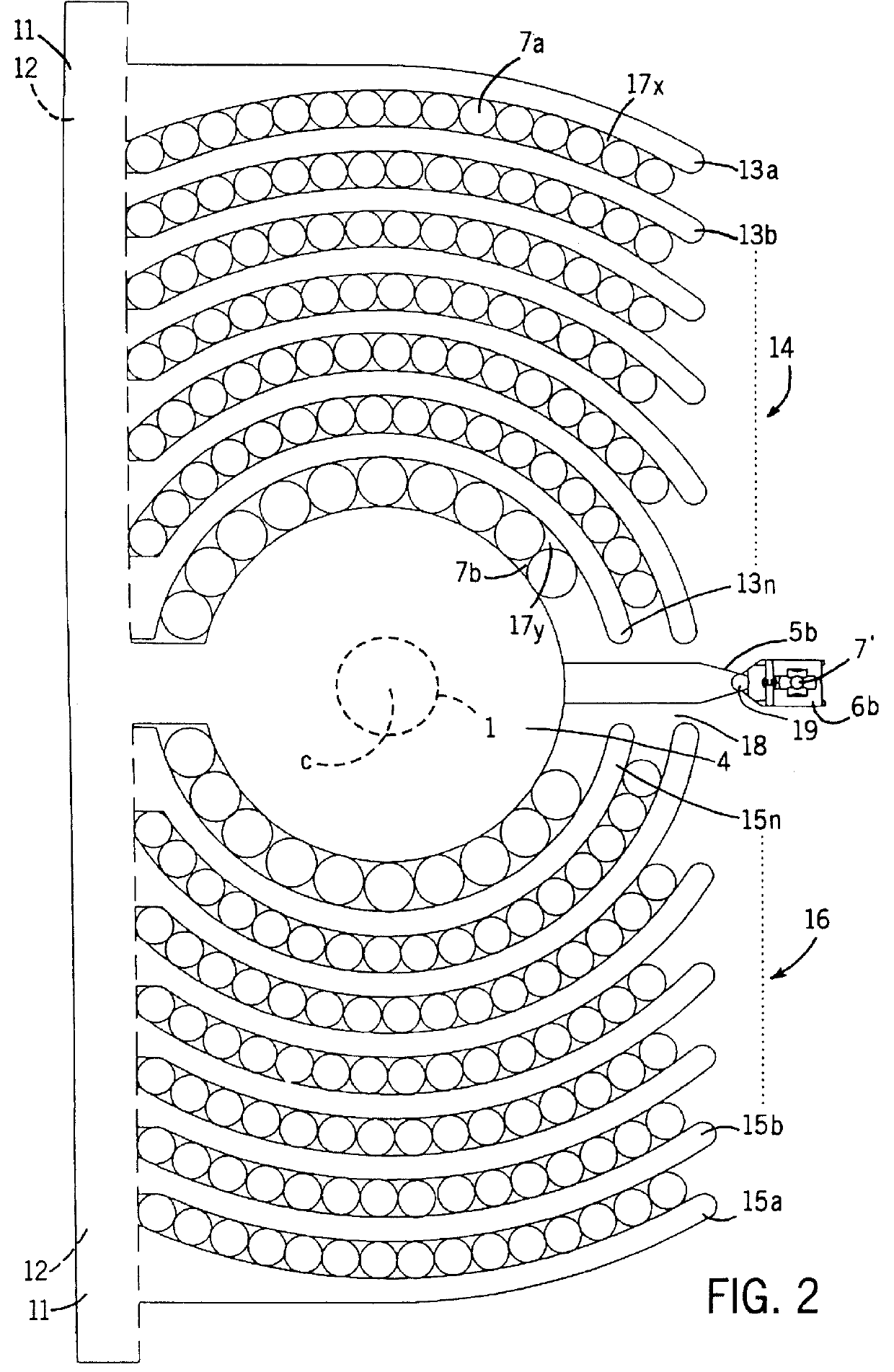
In FIG. 2 there is illustrated a device for storing pipes, according to the invention, and in this Figure there is recognized the finger drilling top structure 4 which can be built together with, respectively comprise a supporting beam 11, provided with a longitudinally extending track 12 within, according to the invention, there are provided one or more curved fingers 13a . . . 13n in a first set 14 and a second unit of curved fingers 15a . . . 15n arranged in a second set 16. It is to be understood that the curved lingers are substantially arranged with the same radius of curvature, which means that between the respective curve fingers there will be defined correspondingly curved storage paths 17x and 17y.

By letting the curved fingers 13a . . . 13n and 15a . . . 15n, respectively, be arranged displaceable in said track 12 in the supporting beam 11, the width between said fingers can be adjusted, such that the width of the storage paths 17x and 17y, respectively, can be adjusted fo...

second embodiment

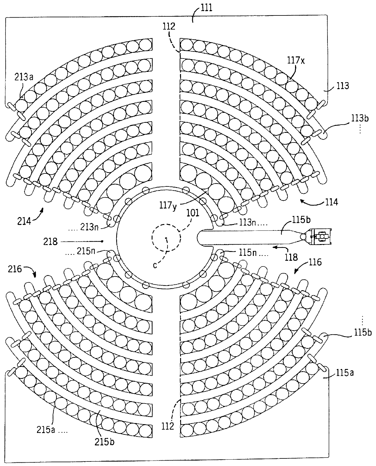
In FIG. 3 there is illustrated a device for storing pipes according to the invention, wherein the pipe handling machine is designated by reference numeral 101 and the finger drilling top structure is designated by reference numeral 111, this embodiment of the finger drill top structure 111 being adapted for four set of curved fingers, namely a first set 114 comprising the finger 113a . . . 113n, and a second set 116 comprising fingers 115a . . . 15n, which fingers at their one end are attached in a channel 112 for mutual displacement and thereby adjustment of the mutually arranged storage paths 17x, 17y.

Said two mentioned sets 114 and 116 will therebetween define a pipe handling opening 118 wherein the upper scissor arm 115b of the pipe handling machine 101 can be brought forward and rearward for fetching and storing of pipes, respectively.

Correspondingly, on the diametrically opposite side of the finger drill top structure 112 there is provided a third set 114 with curved fingers 2...


PUM


Abstract

The present invention relates to a device for storing pipes, especially in vertical position, and for the purpose of providing an improved structure wherein a better utilization of the storage area is achieved, the pipe handling can be effected in a faster and safer manner, and wherein the device can more easily be adjusted for various pipe dimensions, it is according to the present invention suggested that the device comprises an upper supporting means (11; 111) having one or more curved fingers (13a; 113a) for providing arch-shaped storage paths (17x, 17y; 117x, 117y) for pipes (7; 7').

Description

The present invention relates to a device for storing pipes, especially in vertical position.In connection with drilling for oil and gas there are heavy requirements as regards capacity and safety in respect of pipe handling. There exist a plurality of various handling systems on today's market, and the present invention has for an objective to provide an improved device for storing pipes whereby the handling and storing operations can be effected in a rational and appropriate manner.PRIOR ARTIn connection with the stacking of pipes vertically in a derrick, there are specifically two types which will be discussed in the following.A first method is to the fact of positioning the pipes between stationary parallel fingers. This will give a good utilization of the storage area, but there are required four movements of the pipe handling machine.A second method is to the fact of arranging the fingers in a star-shaped pattern, such that the pipe handling machine itself can reside in the mi...

Claims


Application Information

Patent Timeline
IPC IPC(8): E21B19/14E21B19/00
CPCE21B19/14
Inventor RISE, TERJE
Owner RISE TERJE
Why Eureka
Try Eureka