Photovoltaic module assembly

a photovoltaic module and photovoltaic energy technology, applied in photovoltaic energy generation, coatings, instruments, etc., can solve the problems of large amount of manual labor, large area printers used for printing to the connecting pads of the back sheet cannot be positioned accurately over the whole back sheet, and difficulty in fully automating, so as to reduce the area of the isolated pad, reduce the size of the contact pad, and reduce the effect of toleran

Inactive Publication Date: 2016-01-14
VALOE OYJ
View PDF4 Cites 4 Cited by
  • Summary
  • Abstract
  • Description
  • Claims
  • Application Information

AI Technical Summary

Benefits of technology

The present invention is an assembly process for a monolithic photovoltaic module where the interconnecting paste is printed on the photovoltaic cell instead of the conductive circuit element. This process allows for greater precision in the position and shape of the paste, resulting in more efficient electrical connections and improved module efficiency. The use of smaller tolerances in the paste to the cell allows for more accurate features in the electrical connections and reduces the risk of short circuiting. Printing on the cells also provides higher accuracies, resulting in higher yield and reduced contact resistance and improves the module performance by reducing resistance between the contact pad and the paste. The interconnecting paste should be applied during the assembly phase to prevent oxidation during transportation.

Problems solved by technology

This assembly method is difficult to fully automate and thus often involves large amounts of manual labour.
The problem of this method is that the large area printer used for printing to the connecting pads of the back sheet cannot be positioned accurately over the whole back sheet, since the back sheet may comprise large manufacturing tolerances.
The back sheet may be a large object, with surface dimensions of up to 1 m×2 m. Ensuring uniform paste and pressure distribution for the whole area is difficult, leading to uneven size and shape of the interconnecting paste across the whole printing area.
Also the tooling, such as stencils or screens used to apply the interconnecting paste, are large and expensive.
For the large stencil the thermal expansion may lead to significant misalignment of the circuits, contacts on the photovoltaic cells and the interconnecting paste.
As the paste is printed on the back sheet, the shape is not optimal for providing the connection.
After the lamination and the paste curing process poorly defined paste may lead to poor contact not offering enough contact surfaces.
Excessive misalignment, caused by inaccuracies of the process or the placement or shape of the conductive circuit elements, may lead to short circuiting of the complete assembly.

Method used


Image

  • Photovoltaic module assembly
  • Photovoltaic module assembly
  • Photovoltaic module assembly

Examples


Embodiment Construction

[0020]Reference will now be made in detail to the exemplary embodiments of the present invention, examples of which are illustrated in the accompanying drawings.

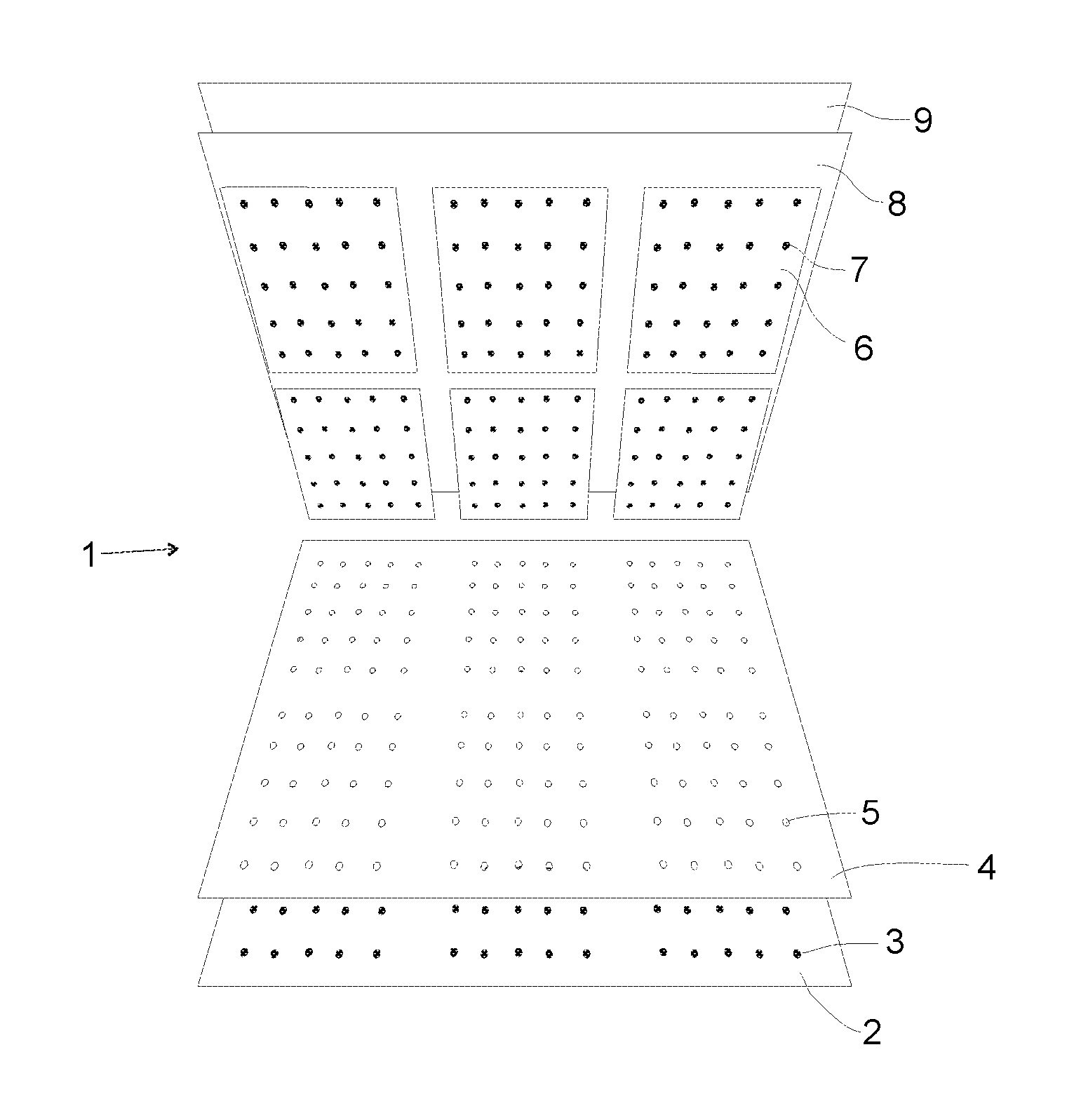
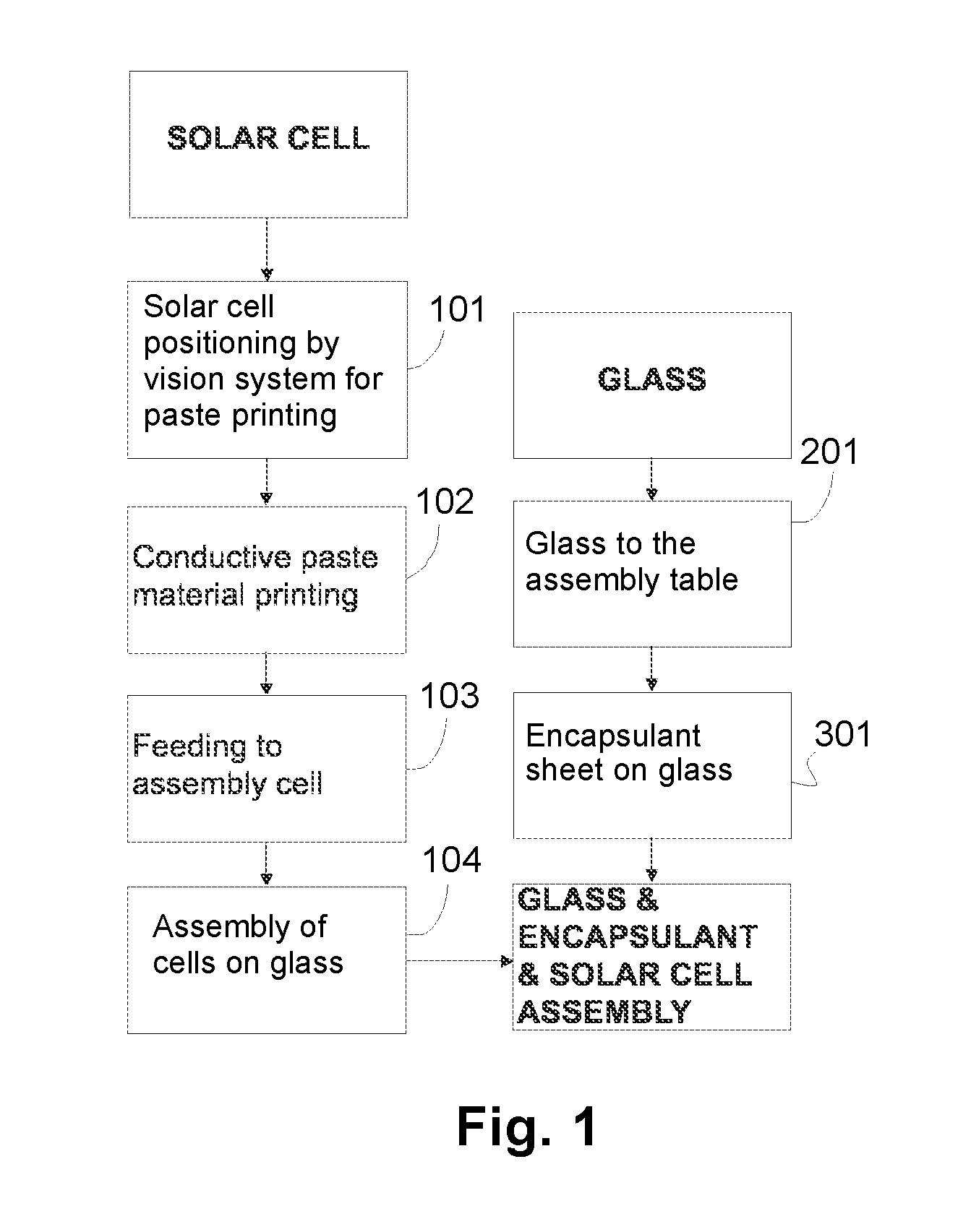
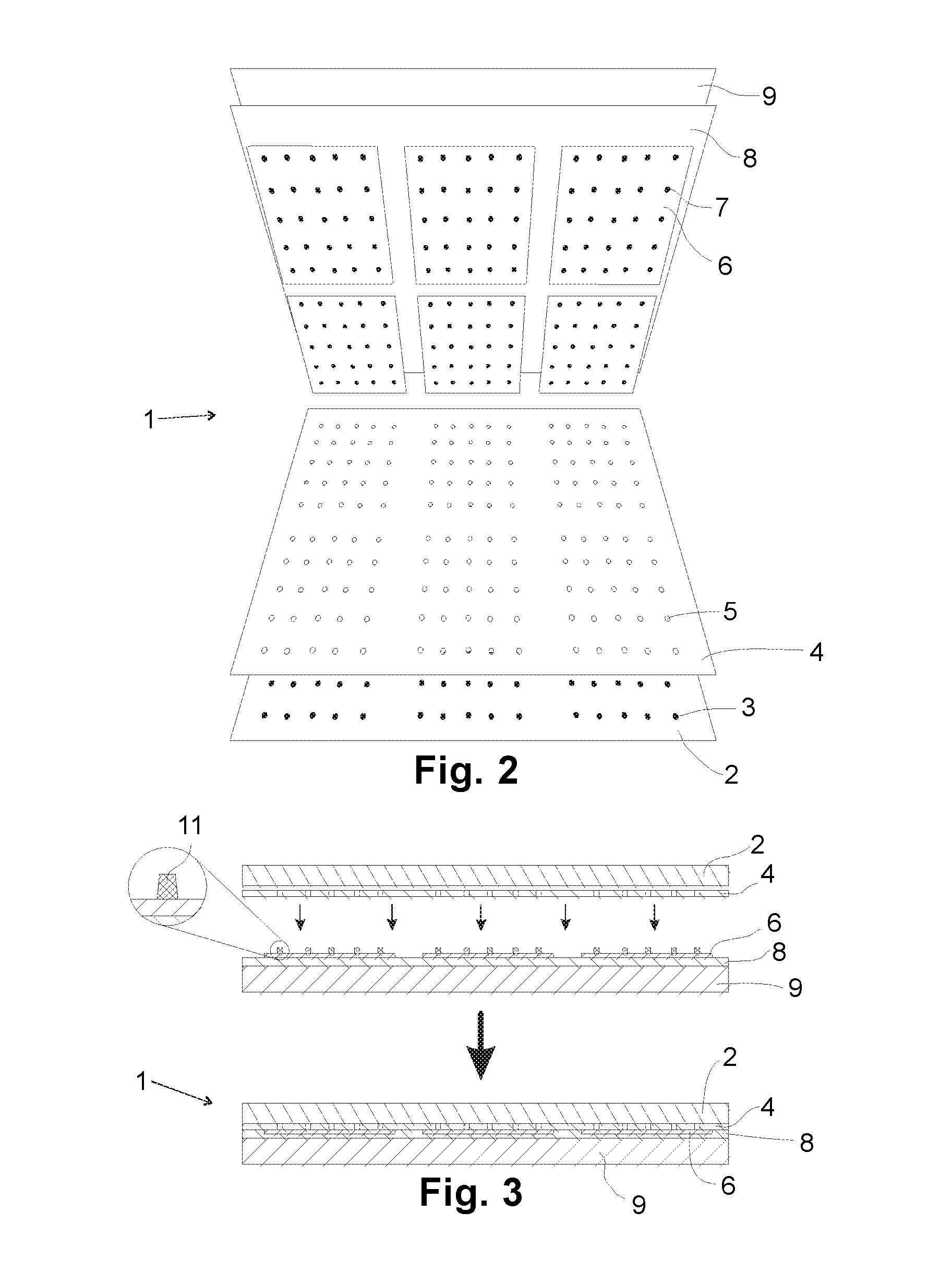
[0021]The photovoltaic module according to the present invention is an assembly comprising several photovoltaic cells that are connected together to increase the amount of power when exposed to light. The assembly usually comprises laminating the components to form a flat and rigid structure. An example of the photovoltaic module is a large flat sandwich structure, comprising a back sheet, conductive circuit elements to which the cells are connected, an encapsulant layer in the form of a sheet of encapsulant material to produce adhesion, mechanical protection and electrical insulation between the layers, photovoltaic cells electrically connected and arranged to be an array, another layer of insulation, typically in the form of another sheet of encapsulant, and the transparent front sheet such as a glass plate. In one example...


PUM

PropertyMeasurementUnit
sizeaaaaaaaaaa
sizeaaaaaaaaaa
conductiveaaaaaaaaaa

Abstract

A method and a system for assembling a photovoltaic module including at least one photovoltaic cell including electrical contacts on the same side of the cell, a back sheet, a sheet of encapsulant material configured to be assembled between the photovoltaic cell and the back sheet and conductive circuit elements between the back sheet and the sheet of encapsulant material. The method includes printing at least one layer of interconnecting paste to the electrical contacts of the photovoltaic cell.

Description

FIELD OF THE INVENTION[0001]The invention relates to photovoltaic modules. More specifically, the invention relates to a method and a system for assembling a photovoltaic module.BACKGROUND OF THE INVENTION[0002]Photovoltaic cells or solar cells are assembled together to form a photovoltaic module. Such modules are also known as solar modules or solar panels. The photovoltaic module is a large area optoelectronic device that converts the energy of light such as solar radiation directly into electricity by the photovoltaic effect.[0003]Photovoltaic modules are commonly manufactured using crystalline silicon cells that are electrically connected in series using tabs and strings. These assemblies are encapsulated to protect the assembly from environment and also to provide safe electrical connections. The top side of the assembly is generally covered with glass and the backside with flexible polymer laminate, though glass can also be used for the back. This assembly method is difficult ...

Claims


Application Information

Patent Timeline
Patent Type & Authority Applications(United States)
IPC IPC(8): H01L31/05H01L31/0224H01L31/048H01L31/049
CPCH01L31/0504H01L31/049H01L31/048H01L31/022441Y02E10/50H01L31/0516B32B17/10018B32B17/10183B32B17/1022B32B17/10788
Inventor PANTSAR, HENRIKKILAMPINEN, VILLESAVIKKO, TIMONIEMINEN, JARKOSAVISALO, TUUKKA
Owner VALOE OYJ
Why Eureka
Try Eureka