Pipe clamp having cable connected clamp members

a technology of pipe clamps and clamp members, which is applied in the direction of soldering apparatus, manufacturing tools,auxillary welding devices, etc., can solve the problems of not being able to conform to misshapen pipes, heavy and cumbersome, and not being able to carry, install or remove by a single individual,

Inactive Publication Date: 2000-06-20
SUMMER MFG
View PDF11 Cites 7 Cited by
  • Summary
  • Abstract
  • Description
  • Claims
  • Application Information

AI Technical Summary

Benefits of technology

It is another feature of the present invention to provide a novel light weight pipe clamp that can be carried and used by a single individual and can be efficiently stored in a small storage area when its use is not needed;
It is also an object of the present invention to provide a novel pipe clamp apparatus having the capability of correcting and aligning misshapen tubular sections through the use of jacking screws so that the ends of the pipe section will fit together precisely;
It is an even further feature of the present invention to provide a novel pipe clamp apparatus which, when assembled to adjacent pipe sections, accomplishes accurate alignment of the pipe sections for welding and also allows access to the welding area to permit efficient welding of the pipe sections while the clamp is installed;
It is another feature of the present invention to provide pipe clamp apparatus having a modularized design to minimize the number of total parts that form the pipe clamp apparatus; and
It is yet another object of the present invention to provide novel pipe clamp apparatus that can be easily stored when not in use and can be stored in flat condition or in rolled up condition depending upon the configuration of the storage space that is available.
Briefly, the various objects and features of the present invention are realized through the provision of pipe clamp apparatus having a parality of pipe clamp elements of rigid construction and which are shaped intermediate the extremities thereof to provide for clearance of the pipe clamp elements with the pipe joint to be welded. The pipe clamping elements are maintained in suitably spaced relation by set screws at each end thereof which engage respective ones of a pair of elongate flexible members, which are preferably defined by flexible cables, but which may conveniently take the form of chain elements or segmented pivotally connected elements within the spirit and scope of the present invention. The pipe clamping elements and cable or flexible elements are assembled to define and elongate flexible pipe clamp assembly which is wrapped about cylindrical objects such as pipes. At one end of the pipe clamp apparatus, one of the clamp elements is provided with a pair of connection hooks. At the opposite end of the elongate pipe clamp apparatus another of the clamping elements is provided with an over-center, cam type or toggle type latch mechanism. The latch mechanism incorporates a clamp connection element having a transverse draw bar that is connected thereto by an adjustment mechanism such as a screw type adjustment. The cam latch mechanism is also provided with a removable latch handle which may be removed after the clamp assembly has been installed to prevent the handle from interfering with welding operations at the pipe joint being welded. The toggle or cam type latch mechanism will apply sufficient force through the flexible cables to the pipe so that minor irregularities in pipe configuration is corrected to permit optimum welded connection thereof. In larger sizes the pipe clamp mechanism may be provided with more than two flexible cables or connectors to provide for sufficient application of force to maintain pipe sections in alignment and to correct minor deficiencies of pipe configuration. Additionally, the pipe clamp apparatus may incorporate other force applying mechanisms such as hydraulic, pneumatic and electrically operated systems for force application.

Problems solved by technology

In most cases the pipe clamping apparatus, especially for aligning and clamping large pipes, is of rigid design and is quite heavy and cumbersome and cannot be carried, installed or removed by a single individual.
Under circumstances where pipe sections are intended to be cylindrical, but are somewhat misshapen due to manufacturing tolerances, manufacturing problems, etc., typical commercially available pipe clamp apparatus is not ordinarily capable of conforming misshapen pipe to a cylindrical configuration to enable its efficient welding.
Typically, commercially available pipe clamp apparatus is not provided with the capability for correcting the roundness of misshapen pipe.
Most commercially available pipe clamp apparatus, especially for clamping large pipe sections, is quite large and cumbersome.
When such pipe clamping apparatus is not being used, it is often difficult to store and handle.
Another problem that is typical with commercially available pipe clamping apparatus is that most pipe clamps will handle only a very limited range of pipe sizes.
This inventory requirement however adds significant cost to overall construction operations.
Another problem that is typical of commercially available pipe clamp apparatus is that the rigid pipe clamp sections that are typically used and the various adjustment mechanisms that are incorporated within each of the pipe sections results in the pipe joint to be welded being somewhat hidden by the pipe clamp apparatus.
This problem significantly adds to the labor costs of the welding operation and therefore is detrimental to overall construction costs.

Method used


Image

  • Pipe clamp having cable connected clamp members
  • Pipe clamp having cable connected clamp members
  • Pipe clamp having cable connected clamp members

Examples


Embodiment Construction

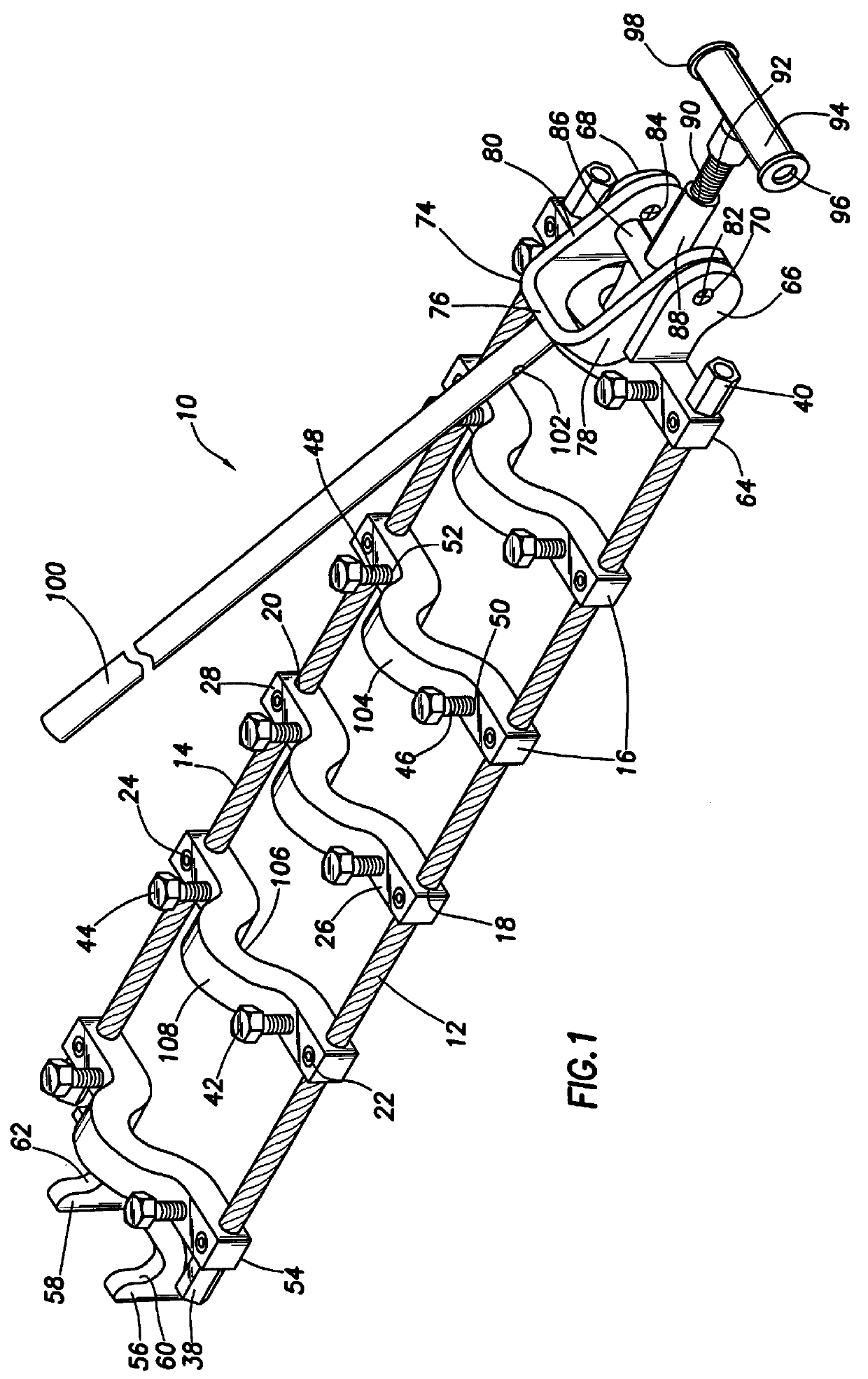
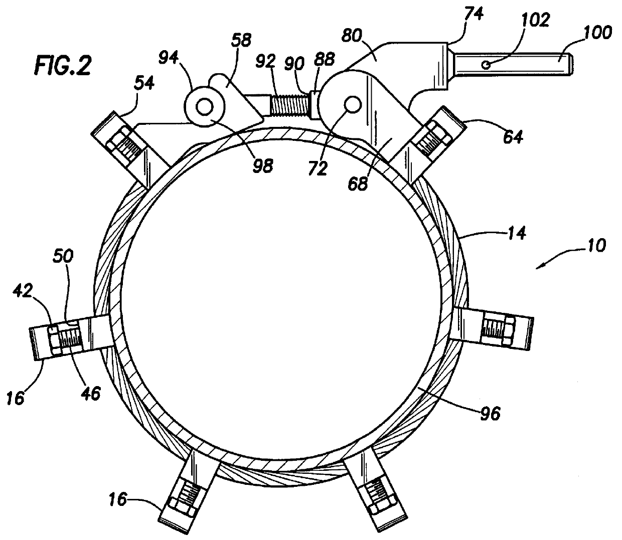
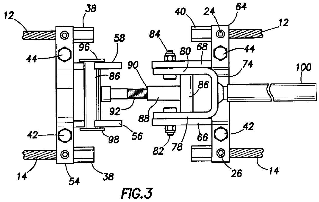
Referring now to the drawings and first to FIG. 1 a flexible pipe clamp constructed in accordance with the principles of the present invention is shown generally at 10 and incorporates a pair of flexible elements 12 and 14 which preferably take the form of flexible wire cable members. It should be borne in mind that the flexible elements may also be defined by interconnected chain links or pivotally interconnected sections of rigid material. It also should be borne in mind that for particularly large pipe sizes the flexible elements 12 and 14 may be defined by two or more flexible elements thereby permitting application of sufficient clamping force to the external surface of the pipe or other cylindrical elements so as to correct minor irregularities in roundness. This feature enables adjacent pipe sections to be positioned in precise registry for welded interconnection thereof. A plurality of pipe clamping elements 16 are located in suitably spaced relation along the flexible cable...


PUM

PropertyMeasurementUnit
Timeaaaaaaaaaa
Lengthaaaaaaaaaa
Forceaaaaaaaaaa

Abstract

An elongate flexible clamp mechanism defines first and second ends and is capable of assume a substantially flat configuration and is capable of being positioned in encircling relation about a cylindrical object such as a pipe. A pair of elongate flexible members such as wire cables, chains or pivotally interconnected rigid members support a plurality of substantially rigid clamping members in spaced relation along the lengths of said elongate flexible members. The clamping members are each provided with jack screws for force applying engagement with the pipe to enable alignment of adjacent pipe sections and to correct minor irregularities in pipe roundness so that adjacent pipe sections can be efficiently welded. The elongate flexible clamp mechanism is provided with first and second latch connector elements which are interconnected when the clamp mechanism is located in encircling relation about the pipe. The latch mechanism is of the cam or toggle type, enabling the clamp mechanism to be tightened about the pipe. Jack screws are also provided on each of the clamping elements to permit jacking force to be applied to the pipe for optimum pipe alignment and for correction of minor irregularities in pipe roundness.

Description

1. Field of the InventionThis invention relates generally to pipe clamp apparatus for clamping cylindrical members such as pipe sections typically to enable welded connection of the cylindrical members. More particularly, present invention is directed to a clamp mechanism for cylindrical objects which is capable of clamping both regular and irregular shapes together and being adjustable to allow for manufacturing tolerances of the cylindrical objects being clamped and to accommodate cylindrical objects of a wide range of sizes. Even more particularly, the present invention concerns pipe clamp apparatus having a plurality of clamp members for engaging cylindrical objects to be clamped and incorporating flexible connectors such as cables, chains or pivotally connected rigid elements for interconnecting and maintaining desired spacing of the clamping members. This invention also involves pipe clamping apparatus incorporating an adjustable latch mechanism for securing the clamp about th...

Claims


Application Information

Patent Timeline
IPC IPC(8): B25B1/00B25B1/20B23K37/04
CPCB23K37/0435B25B1/205B23K2201/06B23K2101/06
Inventor COLLINS, JR., ROBERT H.HELMICK, JAMES E.
Owner SUMMER MFG
Why Eureka
Try Eureka