Projection-type liquid crystal display apparatus

a liquid crystal display and projection-type technology, applied in the direction of television systems, identification means, instruments, etc., can solve the problems of deteriorating dynamic image resolution, response speed lowering, and liquid crystal panel cannot be heated to the optimal operation level

Inactive Publication Date: 2000-06-06
MITSUBISHI ELECTRIC CORP
View PDF19 Cites 28 Cited by
  • Summary
  • Abstract
  • Description
  • Claims
  • Application Information

AI Technical Summary

Benefits of technology

According to a third aspect of the present invention, there is provided a projection-type liquid crystal display apparatus according to the first or the second aspect, further comprising an air fan for allowing air around the liquid crystal light valve means to flow, wherein when the temperature detected by the liquid-crystal temperature detection means is lower than a first predetermined reference temperature, the transparent conductive film is caused to generate heat with the operation of the air fan interrupted, when the temperature detected by the liquid-crystal temperature detection means is not lower than the first reference temperature and lower than a second predetermined reference temperature, the transparent conductive film is caused to generate heat with the air fan being operated, and when the temperature detected by the liquid-crystal temperature detection means is not lower than a second predetermined temperature, the heat generating performance of the transparent conductive film is lowered.
According to a fourth aspect of the present invention, there is provided a projection-type liquid crystal apparatus according to the first aspect, wherein the liquid-crystal display temperature detection means has a plurality of temperature detectors, and the control means controls the heat generating performance of the transparent conductive film in accordance with the total sum of a value obtained by multiplying each of values detected by the plural temperature detectors with a weighting coefficient.

Problems solved by technology

If the above-mentioned conventional projection-type liquid crystal display apparatus is operated in a low-temperature environment, the liquid crystal panel cannot be heated to an optimum operation level.
Thus, there arises problems in that the response speed is lowered, that the resolution of dynamic images deteriorates and a residual image is superimposed and displayed when the frame has been switched.
Also in a case where a liquid crystal panel made of an LCPC (Liquid Crystal Polymer Composite) material which is one of polymer dispersion type liquid crystal is employed, a fact was found that a problem of the hysteresis causing a residual image is superimposed and displayed when a still image has been switched to another frame occurring depending upon the temperature of the liquid crystal panel cannot be overcome.
A projection-type liquid crystal apparatus, of a type having three liquid crystal panels for respectively modulating a red beam, a green beam and a blue beam and then synthesizing the beams to project a color image, has a problem in that the tone of the color image is changed owning to the difference in the temperatures of the respective liquid crystal panels and the difference in the wavelength of the colors.
Another problem arises in that an image forming surface of even one liquid crystal panel encounters temperature inclination along the surface attributable to air flows generated by a cooling fan or the like and the thus the projected image has illuminance inclination.

Method used


Image

  • Projection-type liquid crystal display apparatus
  • Projection-type liquid crystal display apparatus
  • Projection-type liquid crystal display apparatus

Examples


first embodiment

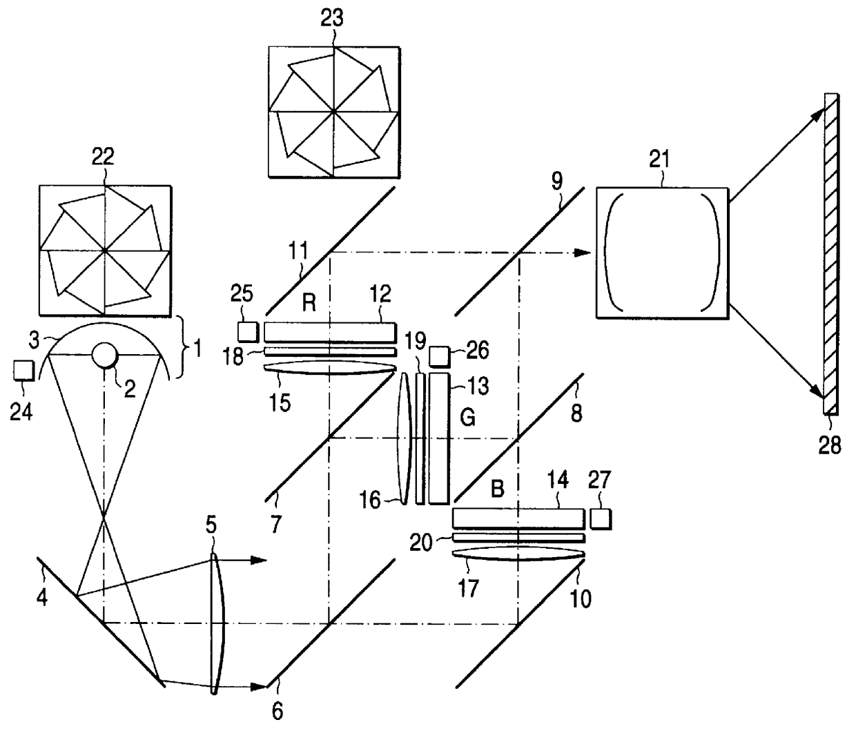
FIG. 1 is a structural-view schematically showing the structure of an optical system of a projection-type liquid crystal display apparatus according to a first embodiment of the present invention. As shown in FIG. 1, the projection-type liquid crystal apparatus according to the first embodiment comprises a light source 1 constituted by a white lamp 2 such as a metal halide lamp, xenon lamp or a halogen lamp and an elliptic mirror 3; a mirror 4 for reflecting a light beam emitted from the light source 1; and a collimator lens 5 for forming the light beam reflected by the mirror 4 into a parallel light beam.

The projection-type liquid crystal apparatus according to the first embodiment has, as a color separating optical system, a dichroic mirror 6 for permitting blue component (B) light to pass through and reflecting other component light and a dichroic mirror 7 for permitting red (R) component light to pass through and reflecting other component light. The projection-type liquid cryst...

second embodiment

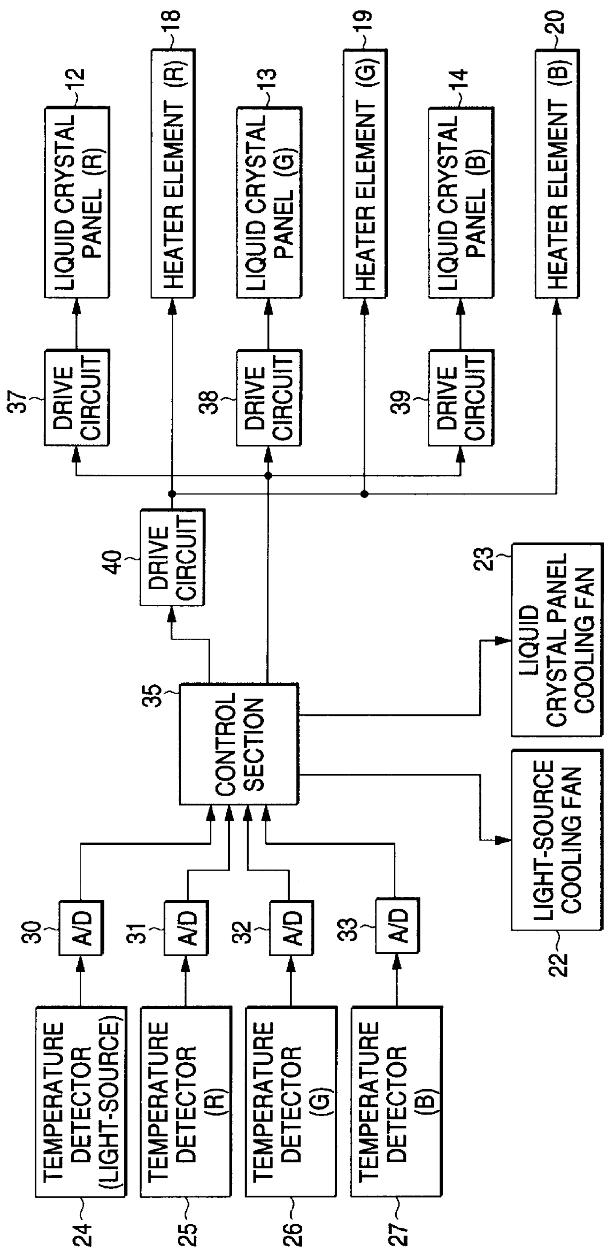
FIG. 7 is a block diagram showing the structure of a control system of a projection-type liquid crystal display apparatus according to a second embodiment of the present invention. Referring to FIG. 7, the same or corresponding structures to those shown in FIG. 2 are given the same reference numerals. The projection-type liquid crystal apparatus according to the second embodiment is different from that according to the first embodiment in that the heater elements 18, 19 and 20 are operated by corresponding drive circuits 40, 41 and 42 and in the contents of control performed by the control unit 35.

Specifically, the projection-type liquid crystal apparatus according to the second embodiment, as shown in FIG. 7, is arranged to individually control the heat generating performance of each of the heater elements 18, 19 and 20 in accordance with values respectively detected by the temperature detectors 25, 26 and 27 for detecting the temperatures of the positions adjacent to the liquid cr...

third embodiment

FIG. 8 is a view of explanatory schematically showing an air duct (a course through which air flows) in the projection-type liquid crystal apparatus according to a third embodiment of the present invention. The projection-type liquid crystal apparatus according to the third embodiment has the same structure as that of the apparatus shown in FIG. 2. Therefore, the third embodiment will be described as well as with reference to FIG. 2. Referring to FIG. 8, the same or corresponding structures to those shown in FIG. 2 are given the same reference numerals.

The projection-type liquid crystal apparatus according to the third embodiment is arranged such that when temperatures (for example, an average value of temperatures detected by the temperature detectors 25, 26 and 27) detected by the temperature detectors 25, 26 and 27 are lower than a predetermined reference temperature t.sub.1, the heat generating performance of the heater elements 18, 19 and 20 is improved to heat the image formin...


PUM

PropertyMeasurementUnit
temperatureaaaaaaaaaa
transparent conductiveaaaaaaaaaa
liquid-aaaaaaaaaa

Abstract

A projection-type liquid crystal display apparatus that prevents deterioration of a projected image occurring attributable to lowering of the temperature of a liquid crystal panel, the difference in the temperature between the liquid crystal panels and temperature inclination in the liquid crystal panel. A projection-type liquid crystal display apparatus having a light source 1, liquid crystal panels 12, 13 and 14 for modulating a light beam emitted by the light source 1, a projection lens 21 for projecting the modulated light beam onto a screen 28, temperature detectors 25, 26 and 27 for detecting the temperatures of portions adjacent to the liquid crystal panels 12, 13 and 14, heater elements 18, 19 and 20 disposed adjacent to image forming surfaces of the liquid crystal panels 12, 13 and 14 and on a light path of a light beam emitted from the light source 1, a drive circuit 40 for operating the heater elements 18, 19 and 20 and a control unit 35 for controlling the heat generating performance of the heater elements 18, 19 and 20 in accordance with values detected by the temperature detectors 25, 26 and 27.

Description

1. FIELD OF THE INVENTIONThe present invention relates to a projection-type liquid crystal apparatus for displaying an image by projecting an image displayed on a liquid crystal panel onto a screen, and more particularly to control of the temperature of a liquid crystal panel and that of temperature inclination occurring in the liquid crystal panel.2. DESCRIPTION OF THE RELATED ARTA conventional projection-type liquid crystal apparatus employing control of the temperature of the liquid crystal panel thereof has been disclosed in, for example, Japanese Utility-Model Publication No. Hei 7-9136. The foregoing apparatus has a liquid crystal panel in the frame thereof and arranged such that a cooling fan is operated in accordance with a value detected by a temperature detector in the frame to stabilize the temperature of the liquid crystal panel.If the above-mentioned conventional projection-type liquid crystal display apparatus is operated in a low-temperature environment, the liquid cr...

Claims


Application Information

Patent Timeline
Patent Type & Authority Patents(United States)
IPC IPC(8): G02F1/13G02F1/133G03B21/16H04N9/31G03B33/12G09F9/00H04N5/74
CPCG02F1/133382G03B21/16H04N9/3197H04N9/312H04N9/3144H04N9/3105
Inventor ASAKAWA, KATSUMIISHITANI, HIROAKITAMANO, KOUHEIYOSHIKAWA, SHIGEHARUMIYATA, AKIHISA
Owner MITSUBISHI ELECTRIC CORP
Why Eureka
Try Eureka