Meander antenna device

a portable radio communication and antenna device technology, applied in the direction of collapsable antenna means, resonant antennas, independent non-interacting antenna combinations, etc., can solve the problems of helical radiators having the problem of strong inter-coupling, reducing the size of antenna radiators, and further reducing bandwidth

Inactive Publication Date: 2000-05-30
LAIRD TECH AB (SE)
View PDF5 Cites 111 Cited by
  • Summary
  • Abstract
  • Description
  • Claims
  • Application Information

AI Technical Summary

Benefits of technology

which solves the problem of providing an antenna means that is mechanically durable and has a geometry suited for location in a small volume. Further objects are to provide substitutes for helical radiators which also give improved antenna performance, to overcome the above-mentioned problem of binding electromagnetic energy in the radiator or radiators of the antenna means, to avoid feed-throughs in a carrier carrying the radiating element(s), to provide an efficient and cost-effective impedance matching means integrated with the antenna means, to provide a configuration which is both efficient and mechanically durable, to enable the use of more precise production techniques that, e.g., wound helices, and to provide an antenna wherein different radiating elements may be combined without being adversely inter-coupled, especially wherein the combination includes an extendable whip antenna.
When the antenna means includes one or more additional radiating element(s), operability within a wider frequency band or two or more separated frequency bands is achieved. It is possible to produce all radiating elements simultaneously in the same sequence of process steps.
The antenna device preferably includes a dielectric carrier carrying the radiating structure to project it outwards from a chassis of a radio communication device on which the device is to be mounted. This enables an efficient radiation pattern. The carrier is preferably a dielectric flexible film or laminate having the radiating structure applied thereon or therein in the form of a conductive film structure, possibly obtained through an etching process. A printing technique is suitable for manufacturing in large quantities.
Especially when the carrier is a flexible film with a printed circuit pattern it is advantageous to integrate on the carrier an impedance matching means for matching impedances of any radiating element on the film or in combination with that structure to circuitry of the radio communication device, usually interfacing at 50 ohms.

Problems solved by technology

A general problem that occurs when the size of an antenna radiator is reduced is a reduction in its relative bandwidth.
However, the loops of a helical antenna generate a magnetic field that binds energy, which results in a further reduction of the bandwidth.
Also, helical radiators have the problem of strong inter-coupling when two or more radiators are arranged close to each other.
That prior art antenna device has the inherent drawbacks of helical antennas, and is difficult and complicated to manufacture because of the need to provide feed-throughs in the substrate or joining conductors at edges.
Although relatively efficient and compact, there is a great variety of prior art antenna devices that involve the above-mentioned problems due to the use of helical radiators.
The problem to be solved thereby is reducing the height of a direction finder antenna, in particular to render it concealable and mobile.
Moreover, the teachings thereof include improving the bandwidth of the antenna by using a conductor having relatively high resistance, leading to a less efficient antenna.
Further, there are no provisions for obtaining a mechanically durable antenna, an antenna suited to fit in a limited volume or an antenna to be combined with other types of antennas.

Method used


Image

  • Meander antenna device
  • Meander antenna device
  • Meander antenna device

Examples


Embodiment Construction

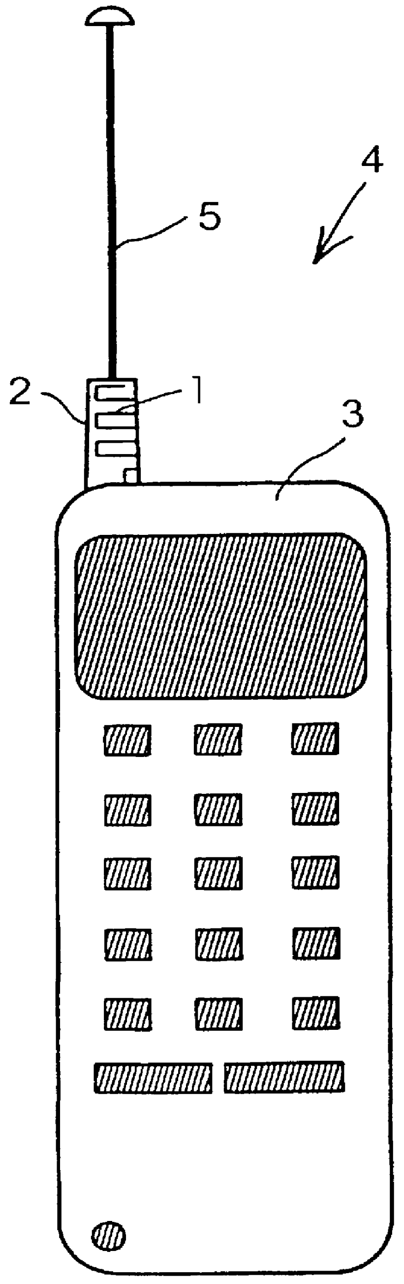
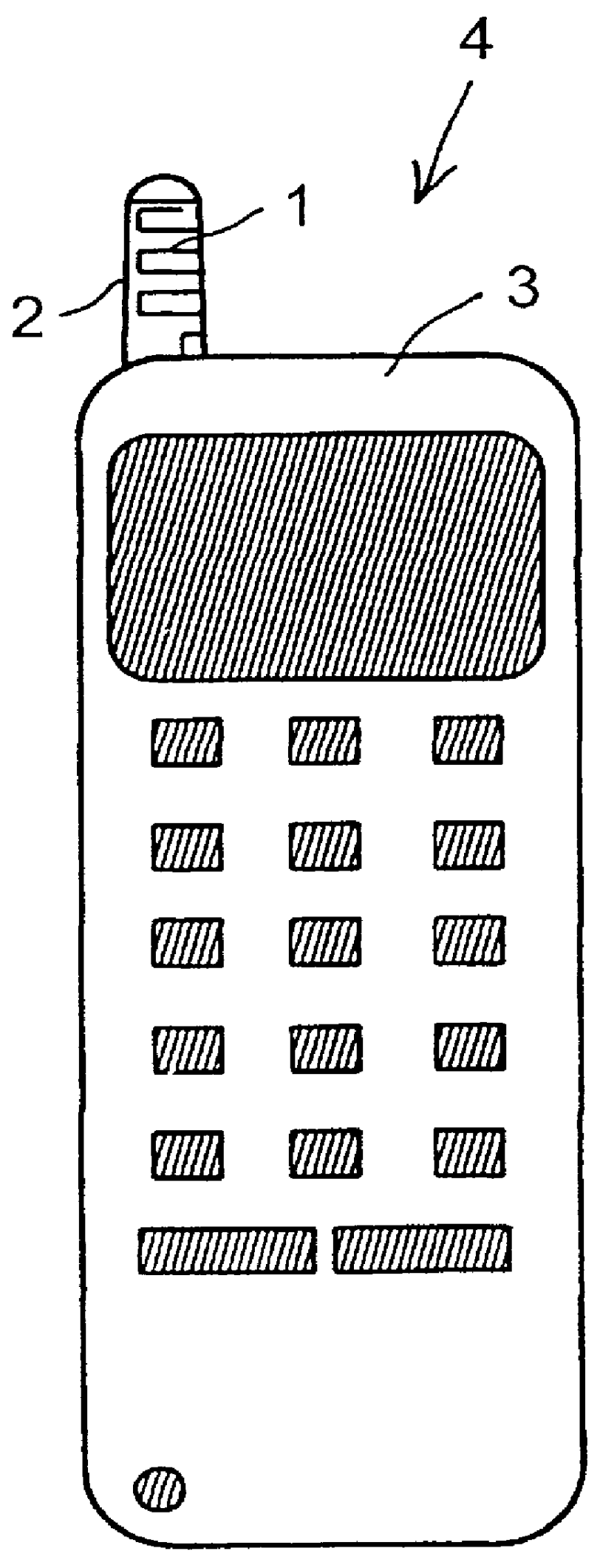
With reference to FIG. 1A, a meander radiating element 1 is carried by a dielectric cylindrical carrier 2 and mounted extending outwards on a chassis 3 of a hand portable mobile telephone 4. The position of the meander element 1 on the chassis 3 is selected such that radiation of the meander conductor 1 is transmitted and received effectively in different positions chosen by an operator during standby or during a telephone call. In FIGS. 1A-B the meander element is located at one side of a top portion of the chassis 3 projecting upwards.

Also shown in FIG. 1A is an extendable and retractable whip antenna 5 shown in its extended position. There may or may not be a whip antenna combined with the meander element, depending on the antenna performance required in a specific case. FIG. 1B shows the arrangement of FIG. 1A having the whip antenna in its retracted position.

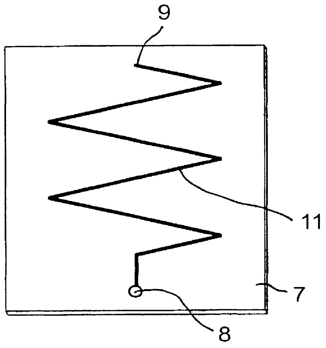
FIG. 2A shows a first possible shape 6 of the meander radiating element being an etched conductor pattern on a dielectric...


PUM


Abstract

An antenna means for a portable radio communication device, in particular a hand-portable mobile telephone, having at least one radiating element that has a meandering and cylindrical configuration. This structure is specifically advantageous in combination with an extendable and retractable whip antenna and, when having two or more meandering radiating elements, in multi-band radiating structures. The antenna device is suitable for manufacturing in large quantities, for example by a flexible printed circuit board technique.

Description

1. Field of the InventionThe present invention relates to an antenna means for a portable radio communication device, comprising a radiating first element tuned to a first frequency, the first element having a central longitudinal first axis, first and second ends being a first feed point and a first open end, respectively, and a meander configuration.Specifically, the invention concerns an antenna means for a hand-portable mobile telephone, which requires a compact and efficient antenna. The inventive antenna means is particularly advantageous when two or more radiating elements are to be combined or when an impedance matching means is required for matching radiating element(s) of the antenna means to transmitter / receiver circuitry of the telephone.2. Description of the Related ArtA general problem that occurs when the size of an antenna radiator is reduced is a reduction in its relative bandwidth. Helically configured radiators are commonly used when antennas are required to fit i...

Claims


Application Information

Patent Timeline
IPC IPC(8): H01Q1/36H01Q1/24H01Q1/10H01Q21/28H01Q1/27H01Q5/10H01Q9/42
CPCH01Q1/36H01Q1/244
Inventor WASS, BO
Owner LAIRD TECH AB (SE)
Why Eureka
Try Eureka