Programmable logic device architecture incorporating a dedicated cross-bar switch

a technology of programming logic and cross-bar switch, which is applied in the direction of computation using denominational number representation, instruments, pulse techniques, etc., can solve the problems of inability to perform any specific function, time-to-market risks associated with the relatively long cycle time necessary, and the inability to use asic based cross-bar switches for reconfigurable applications

Inactive Publication Date: 2000-05-09
ALTERA CORP
View PDF5 Cites 22 Cited by
  • Summary
  • Abstract
  • Description
  • Claims
  • Application Information

AI Technical Summary

Problems solved by technology

When an integrated circuit manufacturer supplies a typical programmable logic device, it is not yet capable of performing any specific function.
Unfortunately, cross-bar switches implemented as ASICs have several disadvantages.
One such disadvantage is the time-to-market risks associated with the relatively long cycle time necessary for the implementation of a new ASIC design.
An additional disadvantage with the use of ASICs for cross bar switches is the fact that ASIC based cross-bar switches cannot be used for reconfigurable applications since ASICs are "hardwired" and must be redesigned for any new application.

Method used


Image

  • Programmable logic device architecture incorporating a dedicated cross-bar switch
  • Programmable logic device architecture incorporating a dedicated cross-bar switch
  • Programmable logic device architecture incorporating a dedicated cross-bar switch

Examples


Embodiment Construction

In the following description, numerous specific details are set forth in order to provide a thorough understanding of the present invention. It will be apparent, however, to one skilled in the art, that the present invention may be practiced without some or all of these specific details. In other instances, well known process steps have not been described in detail in order to not unnecessarily obscure the present invention.

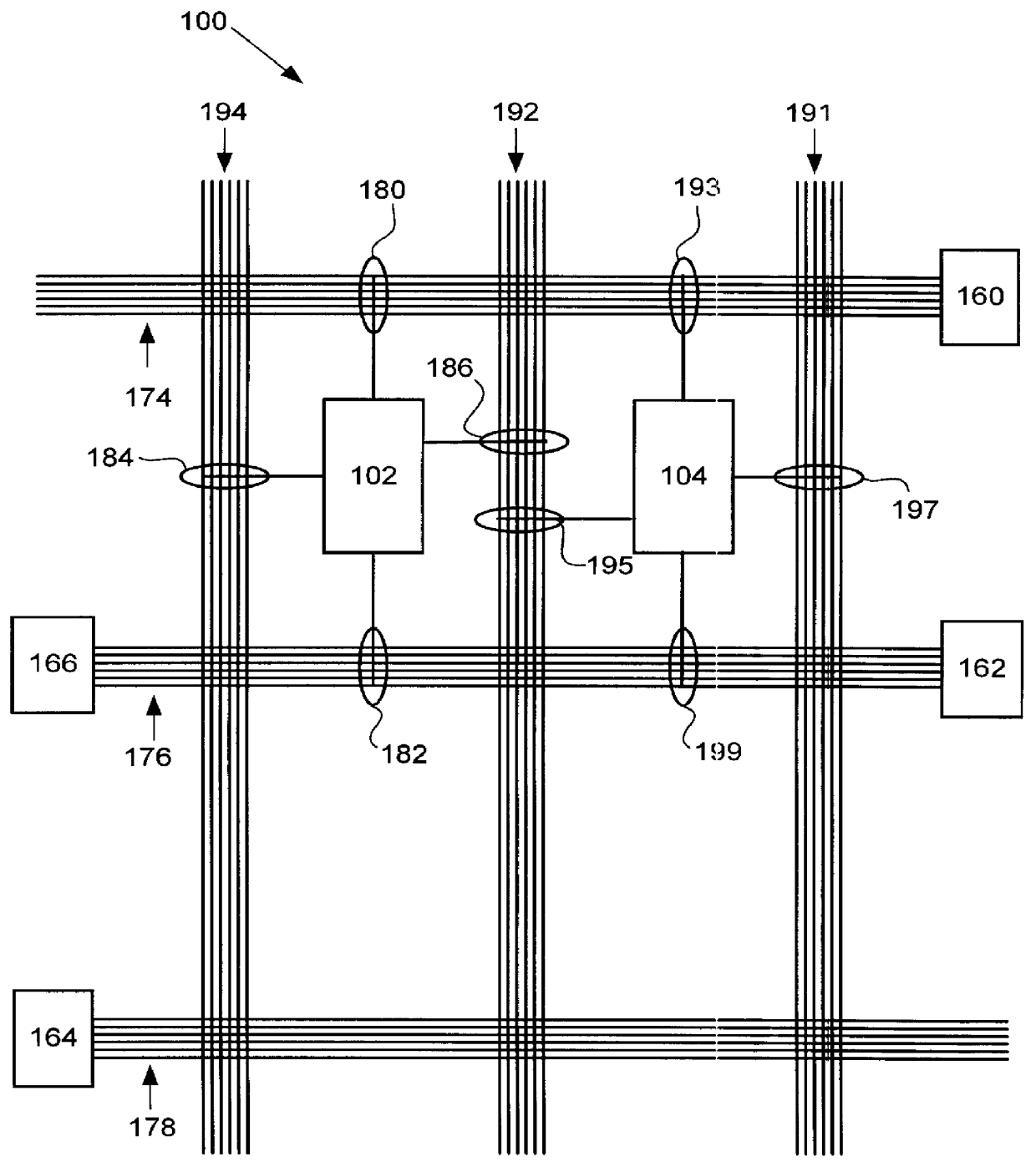
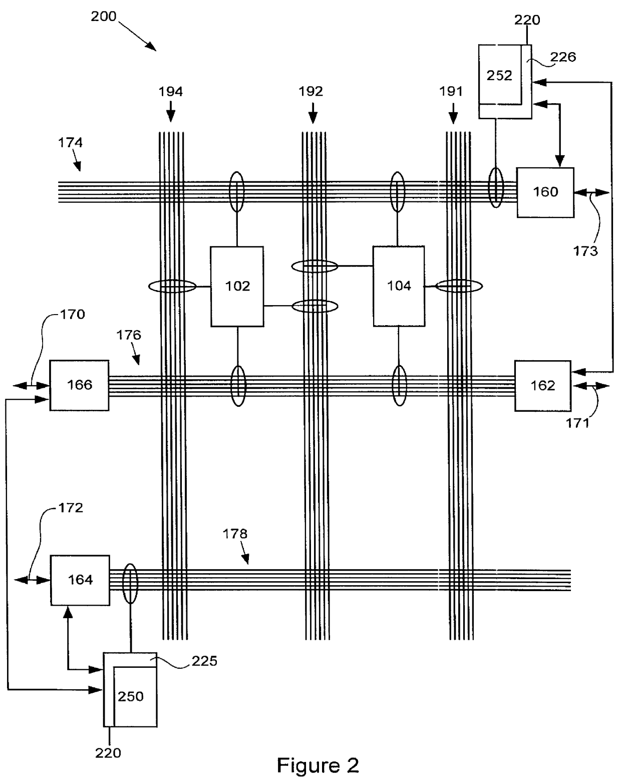
Referring initially to FIG. 2 and FIG. 3, an embedded array type programmable logic device architecture incorporating an interface cross-bar switch in accordance with an embodiment of the invention will be described. FIG. 2 is a functional block diagram of an embedded array type complex programmable logic device CPLD 200. CPLD 200 includes an array of logic blocks 102 programmably coupled to horizontal conductors 174 and 176 as well as vertical conductors 192 and 194. CPLD 200 also includes an associated memory block 104 programmably coupled to a plurality of con...


PUM


Abstract

A programmable logic device architecture incorporating a cross-bar switch is disclosed. In a preferred embodiment, a plurality of logic cells is programmably interconnected to form an array of logic cells capable of implementing complex logic functions. A user selectable cross-bar switch block having dedicated programmable connectors is coupled to the array of logic cells by way of a mode control circuit switch. The mode control circuit switch is arranged to couple the dedicated cross-bar switch block to the array of logic cells in a first mode and to de-couple the cross-bar switch block from the array of logic blocks in a second mode.

Description

1. Field of the InventionThe present invention relates generally to the field of programmable logic devices. More specifically the present invention provides an improved programmable logic architecture by incorporating a reconfigurable dedicated cross-bar switch block capable of independent implementation of complex signal routing and signal processing functions.2. 2. Description of the Related ArtA programmable logic device or PLD is a programmable integrated circuit that allows the user of the circuit, using software control, to customize the logic functions the circuit will perform. The logic functions previously performed by small, medium, and large-scale integration integrated circuits can instead be performed by programmable logic devices. When an integrated circuit manufacturer supplies a typical programmable logic device, it is not yet capable of performing any specific function. The user, in conjunction with software supplied by the manufacturer or created by the user or an...

Claims


Application Information

Patent Timeline
Patent Type & Authority Patents(United States)
IPC IPC(8): H03K19/177
CPCH03K19/1778H03K19/17736
Inventor RANGASAYEE, KRISHNABIELBY, ROBERT N.
Owner ALTERA CORP
Why Eureka
Try Eureka