Method and device for de-icing conductors of a bundle of conductors

Inactive Publication Date: 2000-01-25
ALLAIRE MARC ANDRE +1
View PDF9 Cites 106 Cited by
  • Summary
  • Abstract
  • Description
  • Claims
  • Application Information

AI Technical Summary

Benefits of technology

An object of the present invention is to provide a simple and effective method for de-icing all the conductors of a bundle when needed.
Advantageously, the method and device according to the present invention may be applied to existing conductor bundles of actual power lines while energized and during ice storms, and does not require any interruption of service to clients.
The present method and device are further advantageous in that the system may be completely automatized, autonomous, and without requiring significant workmanship. The device according to the invention can be installed on actual line sections of any length without disturbing the network, and it does not require a heavy or special infrastructure.

Problems solved by technology

In cold regions, ice storms cause melted snow, ice and frost to accumulate on conductors of transmission lines.
The weight of such icy deposits adds to the wind charge and increases the mechanical tension in the conductors, which may cause the cables to sag excessively or break.
These problems are particularly significant with regard to single conductor cables and to bundles of such conductors.
A limited number of de-icing methods have been developed and used by electric utilities to counteract and prevent the formation of ice on high voltage power line cables.
These methods are generally used for ad-hoc de-icing operations in the field and require very expensive workmanship.
Such practice has certain inherent disadvantages, particularly to the needed current load, which requires an enormous amount of power to raise the temperature sufficiently to cause the ice deposit to melt at the cable interface and then shed.
Often, the current supplying capacity of the transmission system is insufficient to accomplish this task and excessively large and expensive auxiliary transformers are then required.
This method is also inconvenient in that the line operation must be interrupted to carry it out.
Another limitation of the already developed thermal methods mentioned above comes from the phase stability of the line, which shall be maintained and assured during its operation.
As can be seen, even if the effectiveness of power line de-icing by using high currents and short circuits is well recognized, all the methods developed up to now have the disadvantage of being very expensive, requiring large power equipment, and necessitating an interruption of the current circulation in the line during the de-icing operation, thereby interrupting service to customers.
Even if these electromagnetic heating wires operate autonomously with great reliability, since there are no mobile parts, and without any service interruption, they have the major disadvantage of consuming energy all year long because they continually dissipate heat, even if the heating decreases by 20% at temperatures over 20.degree. C.
For that reason, this system cannot be used economically for de-icing a whole line; its actual use is limited to melting wet snow of very short sections of line, as those at cross-roads.
In addition, this system requires the replacement of existing cables by new ones which are completely different and thus more expensive to manufacture.

Method used


Image

  • Method and device for de-icing conductors of a bundle of conductors
  • Method and device for de-icing conductors of a bundle of conductors
  • Method and device for de-icing conductors of a bundle of conductors

Examples


Embodiment Construction

Description of a method according to a preferred embodiment of the present invention

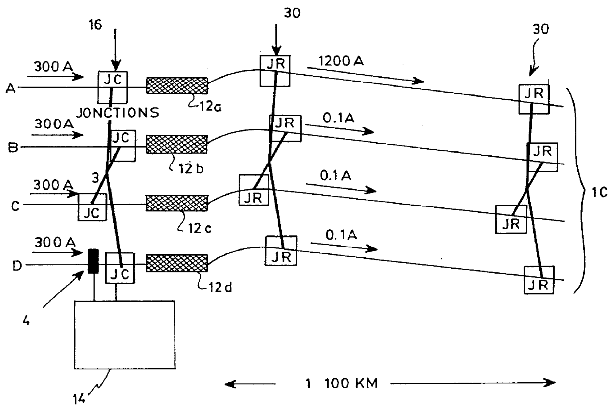
FIG. 1 illustrates a method of de-icing conductors A, B, C and D forming a bundle of conductors 10, in accordance with an embodiment of the present invention. The bundle 10 may be part of a transmission line including a plurality of such bundles. It is understood that although bundle 10 is here shown as including four conductors, the method and device of the present invention may be applied to any group of two conductor or more as long as they are electrically connected together.

The method includes a first step (a) of supplying a total current load in the bundle of conductors 10, the total current load usually being distributed evenly between all the conductors of the bundle 10. This basically constitutes the normal operation of the line. Examples of various current values for the current load in typical conductors of bundles in transmission lines will be given below.

Step (b) of the present method in...


PUM


Abstract

A method and device for removing ice from overhead conductors of a bundle of conductors or preventing an accumulation of ice on these conductors. The method includes forcing the entire current load of the line in one or a portion of the conductors, the excessive power dissipated in this manner de-ices the conductor by Joule heating. The method is repeated for different conductors of the bundle until they have all been de-iced or for the entire duration of an ice storm. Electric power units are provided on each conductor to control the current circulation as needed, and a command module controls the entire system. Conducting elements are provided at the beginning and at the end of the line to allow a distribution of the current as needed.

Description

The invention relates to a method and a device for sequentially de-icing the conductors of a bundle of conductor through heating.In cold regions, ice storms cause melted snow, ice and frost to accumulate on conductors of transmission lines. The weight of such icy deposits adds to the wind charge and increases the mechanical tension in the conductors, which may cause the cables to sag excessively or break. These problems are particularly significant with regard to single conductor cables and to bundles of such conductors. Bundles of conductor cables comprise a plurality of individual conductors, usually spaced-apart or separated from each other by means of spacers to provide better electrical characteristics.A limited number of de-icing methods have been developed and used by electric utilities to counteract and prevent the formation of ice on high voltage power line cables. Conventional practices for avoiding or limiting the formation of ice generally comprise mechanically shocking ...

Claims


Application Information

Patent Timeline
IPC IPC(8): H02G7/16H05B3/54H05B3/56
CPCH02G7/16H05B3/56H05B2214/02
Inventor ALLAIRE, MARC-ANDRELAFORTE, JEAN-LOUIS
Owner ALLAIRE MARC ANDRE
Why Eureka
Try Eureka