
Wireless room occupancy monitor

a monitor and wireless technology, applied in the field of real-time location systems, can solve the problems of non-standard ir and ultrasound technology, low accuracy, and cost of deployment, and achieve the effect of room-level accuracy

Pending Publication Date: 2022-11-17
EMANATE WIRELESS
View PDF0 Cites 0 Cited by
  • Summary
  • Abstract
  • Description
  • Claims
  • Application Information

AI Technical Summary

Benefits of technology

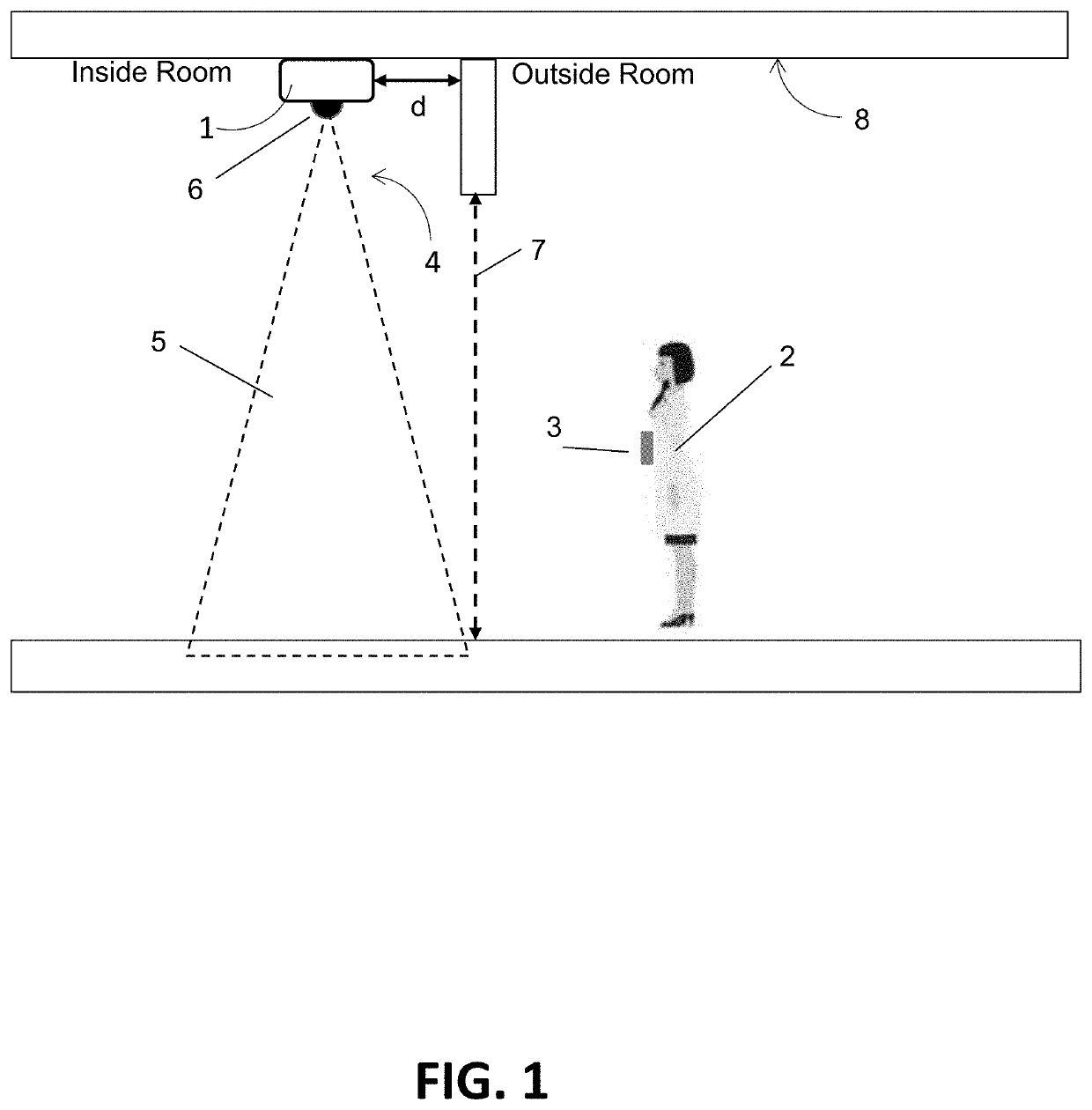
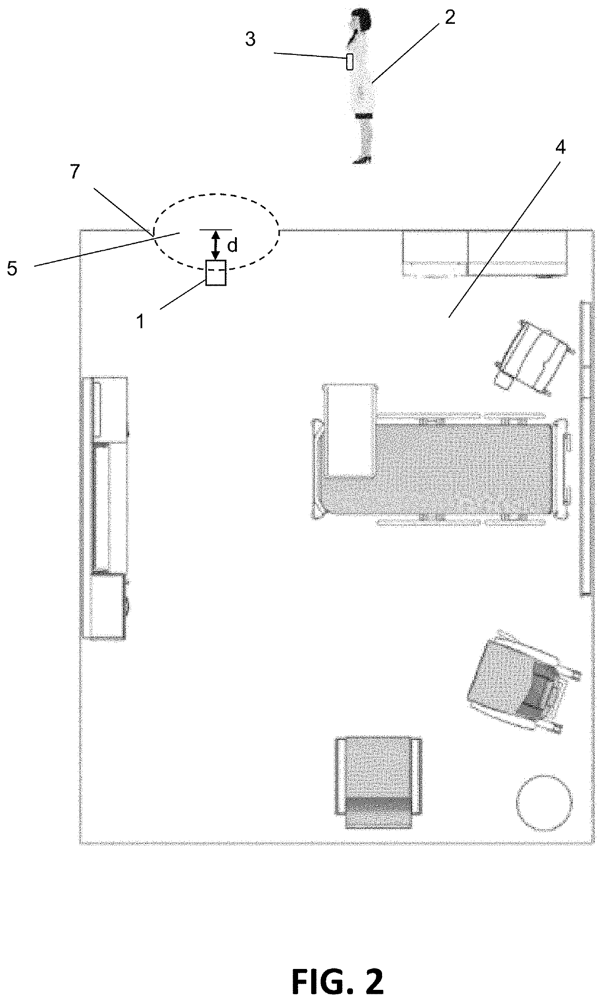
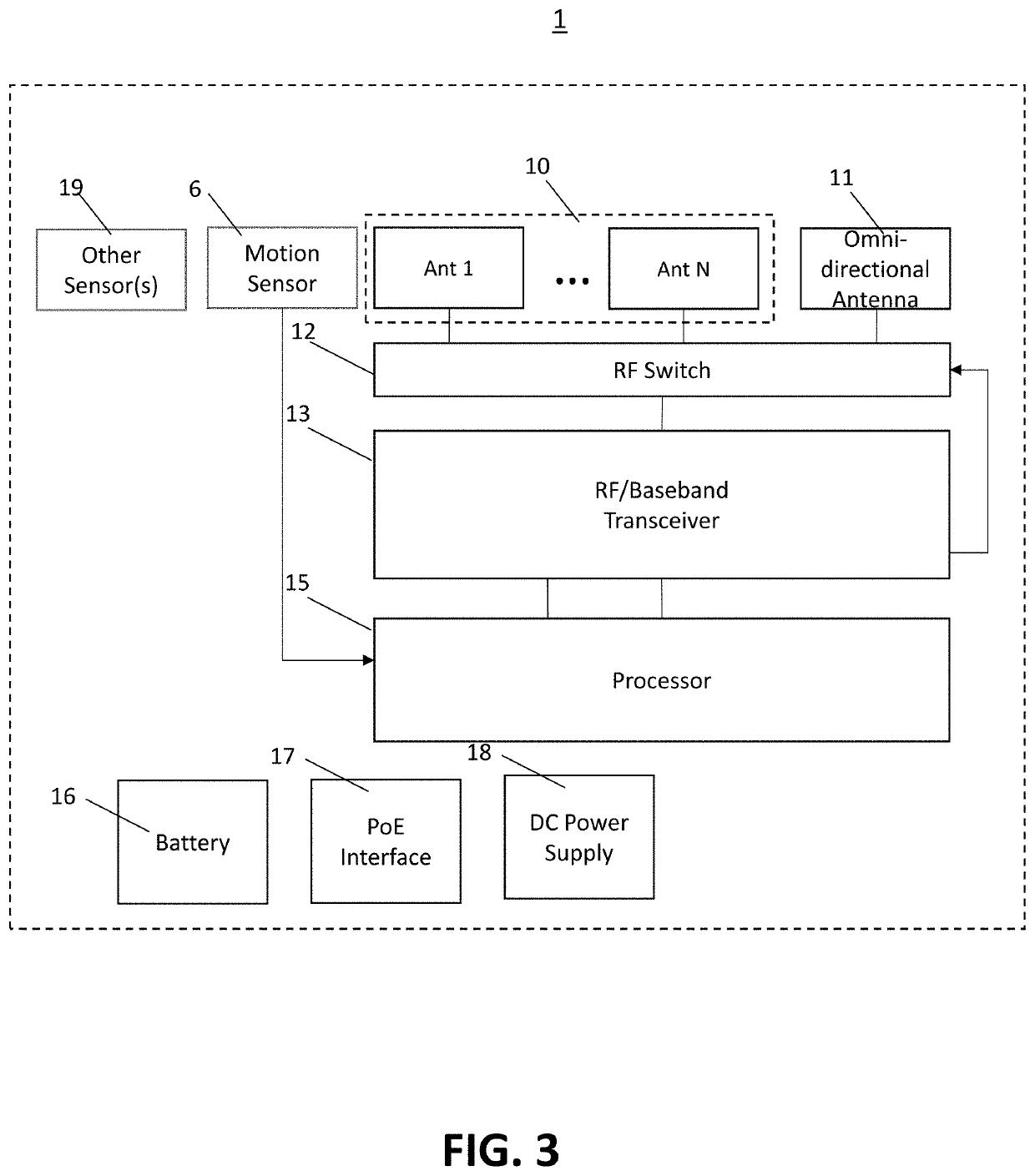
The present patent describes a wireless RF-based RTLS (real-time location system) that can provide room-level accuracy for detecting the presence of tag devices in a room. The system includes an antenna array mounted on the ceiling of the room, a wireless transceiver, a processor, and a motion sensor. The motion sensor wakes up the processor when the tag device enters or exits the room, and the processor activates the wireless transceiver to receive the wireless transmissions from the tag device. The algorithm on the received signal strength estimates and array response vectors derived from the receive signals determines when the tag device has entered or exited the room via the entryway. The system can detect room entries and exits with high accuracy. The method includes training a machine learning algorithm using ground truth information and data descriptive of the receive signals. The technical effects include improved accuracy and efficiency for room occupancy monitoring.

Problems solved by technology

Obviously, if the RTLS did not very accurately detect that the nurse entered the correct room at the correct time, the RTLS would not be very useful for this application.
Both IR and ultrasound technologies are non-standardized, costly to deploy and less energy efficient than BLE-only RTLS's.

Method used


Image

  • Wireless room occupancy monitor
  • Wireless room occupancy monitor
  • Wireless room occupancy monitor

Examples


Embodiment Construction

[0034]From the above description, those skilled in the art will perceive improvements, changes and modifications. Such improvements, changes and modifications are within the skill of one in the art and are intended to be covered by the appended claims.

[0035]Presented herein is a Room Occupancy Monitor and a Room Occupancy Monitoring System. The Room Occupancy Monitor is, in one form, a battery-powered device that can be installed inside a room and configured to receive transmissions from one or more wireless tag devices to determine when any of the tag devices enter or exit the room. The monitor could be installed in a hospital patient room, for example, and used in a nurse-call cancellation application / use case to determine when a nurse wearing a wireless (e.g., Bluetooth™ wireless 5.1) tag or badge has entered a room to visit a patient and automatically cancel the pending nurse call request at the nurse's station. It could alternatively be used in automated hand hygiene compliance...


PUM


Abstract

A wireless room occupancy monitor, system and training method are provided. The room occupancy monitor includes an antenna array configured to detect wireless transmissions from a tag device; a wireless transceiver configured to receive the wireless transmissions detected by the antenna array and produce receive signals; a processor configured to process the receive signals; and a motion sensor coupled to the processor and configured to wake up the processor in response to detecting when the tag device enters or exits a room. The monitor is configured to be mounted proximate an entryway to the room. After the motion sensor wakes up the processor, the processor is configured to power on the wireless transceiver and run an algorithm on a sequence of received signal strength estimates and array response vectors derived from the receive signals to determine when the tag device has entered or exited the room via the entryway.

Description

CROSS-REFERENCE TO RELATED APPLICATIONS[0001]This application claims the benefit of U.S. Provisional Patent Application No. 63 / 182,071, filed Apr. 30, 2021; U.S. Provisional Patent Application No. 63 / 196,276, filed Jun. 3, 2021; U.S. Provisional Patent Application No. 63 / 236,288, filed Aug. 24, 2021; and U.S. Provisional Patent Application No. 63 / 308,160, filed Feb. 9, 2022, which are incorporated by reference herein in their entirety.FIELD OF THE INVENTION[0002]The present disclosure relates generally to real-time location systems (RTLSs) and, more specifically, to monitoring systems that can locate active radio-frequency identification (RFID) tags in real-time.BACKGROUND OF THE INVENTION[0003]There is a strong market need for real-time location systems (RTLSs) that can deliver room-level accuracy. Healthcare automation applications such as those used for hand hygiene enforcement or nurse call cancellation demonstrate this need. For example, when a patient presses a nurse call butt...

Claims


Application Information

Patent Timeline
Patent Type & Authority Applications(United States)
IPC IPC(8): H04W4/029H04W4/33
CPCH04W4/029H04W4/33H04W4/80
Inventor SUGAR, GARY L.TESFAI, YOHANNESVAIDYANATHAN, CHANDRADIENER, NEIL R.
Owner EMANATE WIRELESS
Learn More