Eureka AIR delivers breakthrough ideas for toughest innovation challenges, trusted by R&D personnel around the world.

Branched wire harness manufacturing method

Pending Publication Date: 2022-11-17
AUTONETWORKS TECH LTD +2
View PDF0 Cites 0 Cited by
  • Summary
  • Abstract
  • Description
  • Claims
  • Application Information

AI Technical Summary

Benefits of technology

The patent text describes a way to make a wire harness that is simpler and has fewer parts. This means that it may be easier and more cost-effective to create.

Problems solved by technology

With the method of sandwiching the waterproof block between adjacent electric wires, when the number of connected electric wires increases, the task of sandwiching the waterproof blocks one by one between the adjacent electric wires requires labor, thus complicating the manufacturing step.
Also, the number of parts increases and the manufacturing cost increases.
Also, in the method of attaching a waterproof spacer with an insertion hole and the method of using a waterproof covering having a branch tube portion, it is necessary to newly create a member when the number or size of the connected electric wires is changed, and thus the manufacturing step becomes complicated.

Method used


Image

  • Branched wire harness manufacturing method
  • Branched wire harness manufacturing method
  • Branched wire harness manufacturing method

Examples


embodiment

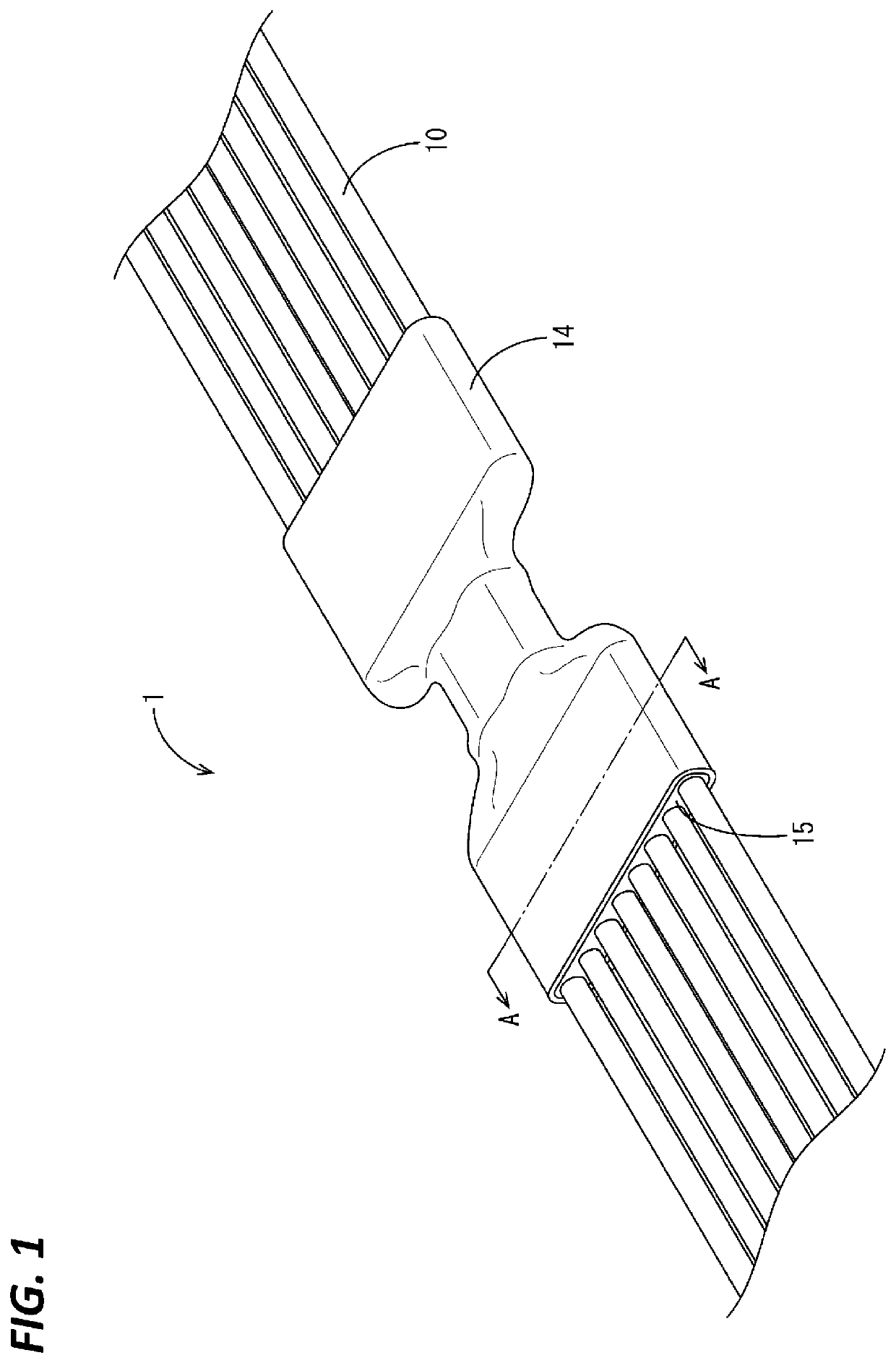
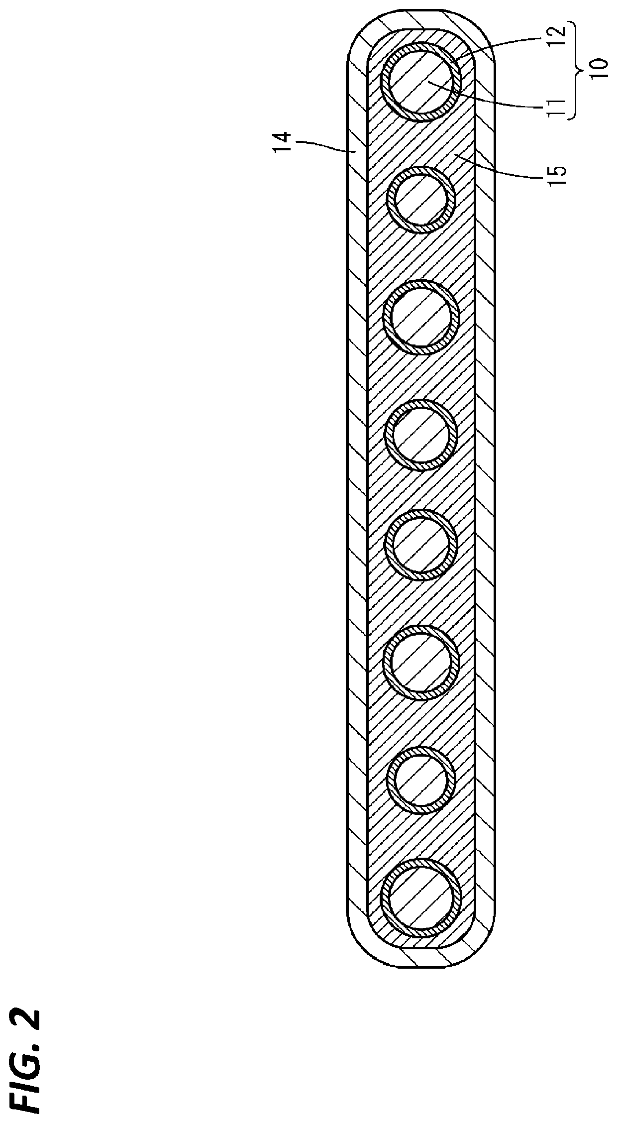
[0026]An embodiment will be described with reference to FIGS. 1 to 8. As shown in FIG. 1, the branched wire harness 1 of the present embodiment includes a plurality of electric wires 10 connected to each other, a waterproof covering 14, and a waterproof material 15.

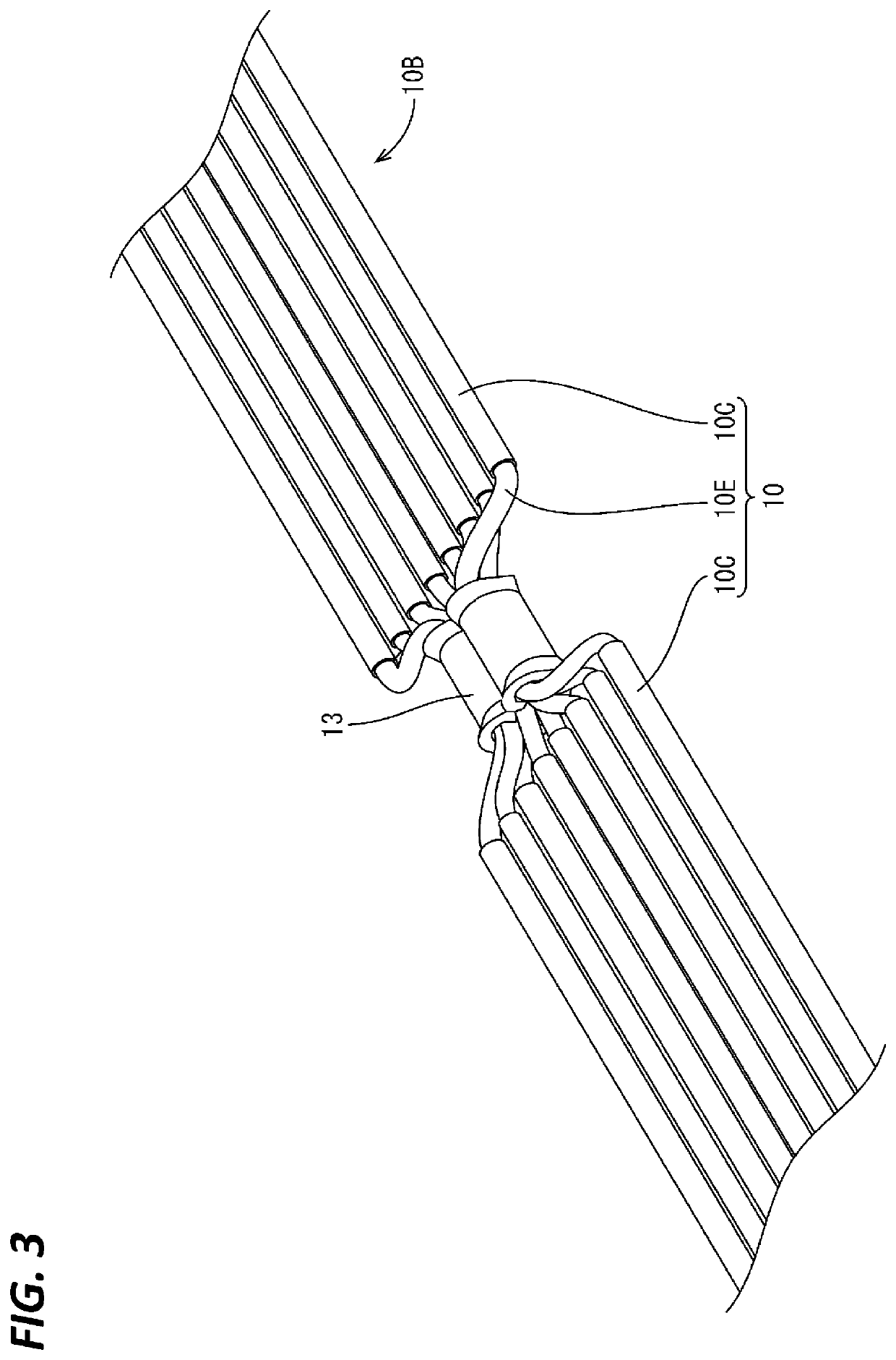
[0027]As shown in FIG. 2, each of the plurality of electric wires 10 includes a core wire 11 constituted by a stranded wire obtained by twisting together a plurality of metal strands, and an insulating covering 12 made of synthetic resin that covers the core wire 11. As shown in FIG. 3, each electric wire 10 has a covered portion 10C at which the core wire 11 is covered with the insulating covering 12, and an exposed portion 10E at which the insulating covering 12 is stripped off and the core wire 11 is exposed. The exposed portion 10E is arranged at an intermediate portion between both ends of the electric wire 10.

[0028]As shown in FIG. 3, the plurality of electric wires 10 are electrically connected due to the core wire...

first modified example

[0042]In the waterproof material attachment step, as shown in FIG. 9, two or more spring-shaped waterproof materials 20 may be attached to the covered portions 10C of the plurality of electric wires 10 adjacent to one end of the exposed portions 10E (the lower left end of FIG. 9). Similarly, two or more spring-shaped waterproof materials 20 may be attached to the covered portions 10C of the plurality of electric wires 10 adjacent to the other end of the exposed portions 10E (upper right end in FIG. 9).

second modified example

[0043]Hereinafter, another example of a method for manufacturing the spring-shaped waterproof material 20 will be described. First, as shown in FIG. 10, a linear waterproof strand 50 made of a material that is softened by heating is wrapped in a spiral shape around a round bar-shaped iron core 51. Next, the waterproof strand 50 wrapped around the iron core 51 is heated. Next, the heated waterproof strand 50 is rapidly cooled, whereby the shape of the waterproof strand 50 is fixed in a spiral shape. After cooling, the iron core 51 is pulled out to obtain the spring-shaped waterproof material 20. The outer diameter and wrapping pitch of the waterproof strand 50, the outer diameter of the iron core 51, and the like can be set as appropriate according to the inner diameter, outer diameter, wire diameter, pitch, and the like of the spring-shaped waterproof material 20 to be obtained.

Other Embodiments

[0044](1) In the above-described embodiment, in the plurality of electric wires 10, the e...


PUM


Abstract

A method for manufacturing a branched wire harness 1 includes a connection step of bundling and connecting core wires 11 of a plurality of electric wires 10 including the core wires 11; a waterproof material attachment step of attaching, to the plurality of electric wires 10, a spring-shaped waterproof material 20 constituted by a material that is softened or melted through heating; a covering step of covering, with a waterproof covering 14, the plurality of electric wires 10 to which the spring-shaped waterproof material 20 is attached; and a heating step of softening or melting the spring-shaped waterproof material 20 through heating, and filling in a gap between the waterproof covering 14 and the electric wires 10, or a gap between the adjacent electric wires 10.

Description

TECHNICAL FIELD[0001]The technique disclosed by the present specification relates to a branched wire harness manufacturing method.BACKGROUND[0002]A branched wire harness in which core wires of a plurality of electric wires are bundled and electrically connected is known. In this type of branched wire harness, a region where the core wire is exposed from the insulating covering of the electric wire is covered with a waterproof covering such as a heat-shrinkable tube to prevent the exposed region from being exposed to water. However, if there is a large number of electric wires, if electric wires with different outer diameters are connected to each other, or the like, there is concern that water will enter through a gap between the electric wires or a gap between the electric wires and the waterproof covering. In order to solve this problem, a method of sandwiching a waterproof block between adjacent electric wires (see Patent Document 1), a method of attaching a waterproof spacer hav...

Claims


Application Information

Patent Timeline
IPC IPC(8): H01B13/012H01R4/72
CPCH01B13/01281H01R4/72H01B13/01254H01B13/012H01B13/01263H02G1/14Y02A30/14H01B7/285
Inventor KAWATA, YUJIMIYAMOTO, KENJI
Owner AUTONETWORKS TECH LTD
Why Eureka
Eureka Blog
Learn More