Edge Phase Effects Removal Using Wavelet Correction and Particle Classification Using Combined Absorption and Phase Contrast

a technology of particle classification and wavelet correction, applied in the direction of image enhancement, material analysis using wave/particle radiation, instruments, etc., can solve the problems of difficult quantification of volume fractions of each material phase within bulk samples, difficult classification of individual material phases, and inconvenient us

Active Publication Date: 2022-11-17
CARL ZEISS X RAY MICROSCOPY
View PDF1 Cites 0 Cited by
  • Summary
  • Abstract
  • Description
  • Claims
  • Application Information

AI Technical Summary

Benefits of technology

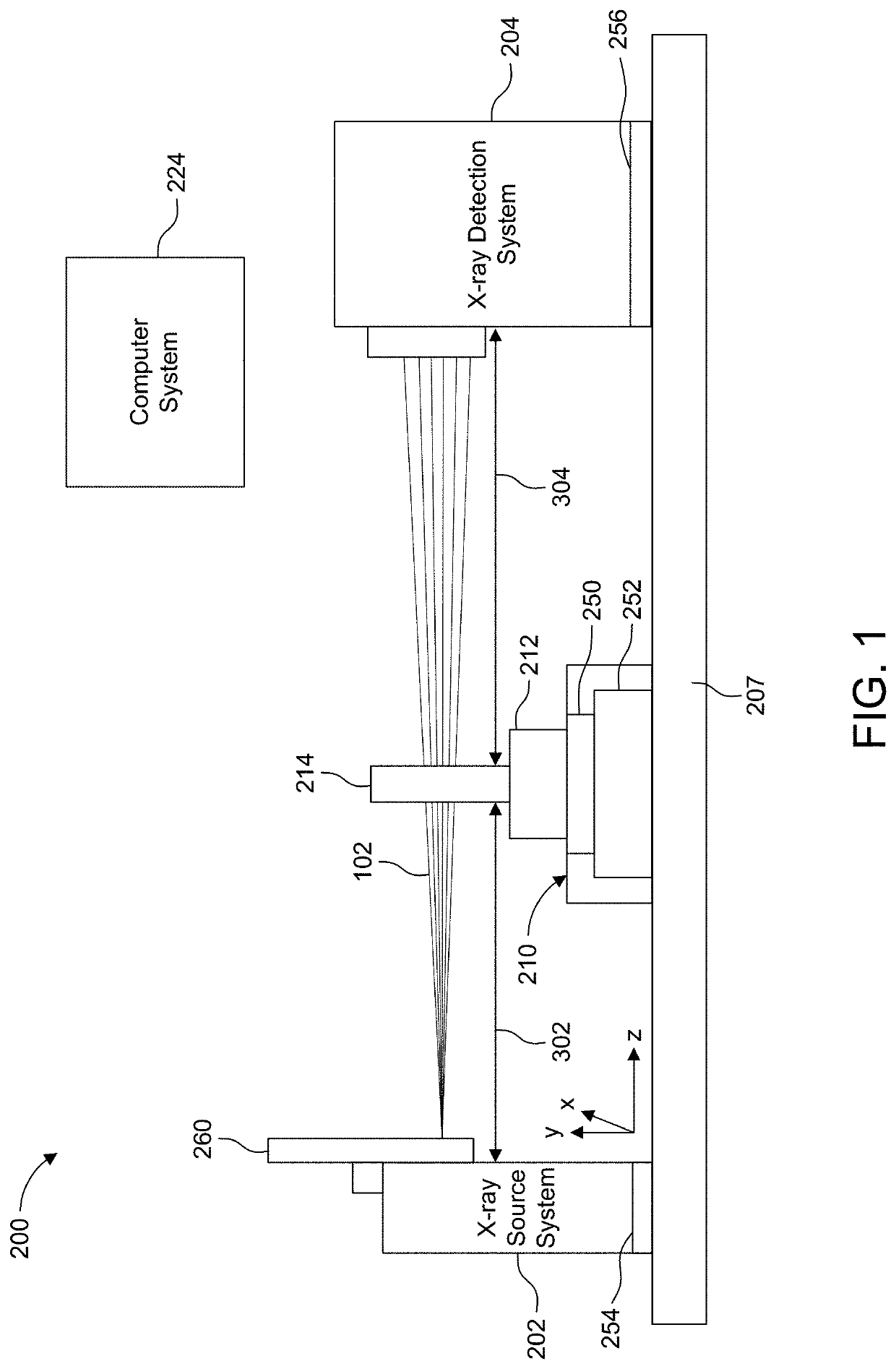
[0006]The present approach employs X-ray analysis and possibly computed tomography. 3D X-ray tomography can provide very fast volumetric classification of particles by scanning large volumes of a given sample in a single scan. However, the minimal density differences between the material phases pose immense challenges in discerning different material phases since the x-ray absorption contrast between the two material phases is extremely low. When even low density particles are imaged in X-ray tomography at sufficiently high resolution, even on scanners using laboratory-based polychromatic x-ray tubes, the reconstructed image slices demonstrate distinct phase signals or fringes around the edges of the particles that obscure whatever minimal absorption contrast differences exist in the resultant tomography slices.
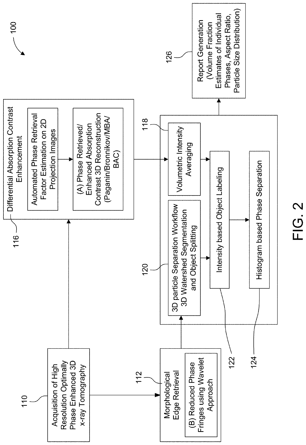
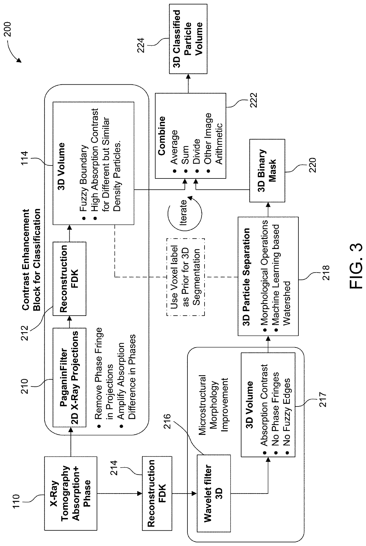
[0021]In a possible automated process, the wavelet based filtering includes estimating wavelet width via automated measurement on a subvolume. This could be achieved by performing a series of wavelet deconvolutions at a variety of strengths and selecting a strength that maximizes signal to noise ratio.

Problems solved by technology

However, the minimal density differences between the material phases pose immense challenges in discerning different material phases since the x-ray absorption contrast between the two material phases is extremely low.
In mixed formulations consisting of mixed material phase microscopic particles, the classification of individual material phases and quantification of volume fractions of each material phase within the bulk samples has been challenging.

Method used


Image

  • Edge Phase Effects Removal Using Wavelet Correction and Particle Classification Using Combined Absorption and Phase Contrast
  • Edge Phase Effects Removal Using Wavelet Correction and Particle Classification Using Combined Absorption and Phase Contrast
  • Edge Phase Effects Removal Using Wavelet Correction and Particle Classification Using Combined Absorption and Phase Contrast

Examples


Embodiment Construction

[0044]The invention now will be described more fully hereinafter with reference to the accompanying drawings, in which illustrative embodiments of the invention are shown. This invention may, however, be embodied in many different forms and should not be construed as limited to the embodiments set forth herein; rather, these embodiments are provided so that this disclosure will be thorough and complete, and will fully convey the scope of the invention to those skilled in the art.

[0045]As used herein, the term “and / or” includes any and all combinations of one or more of the associated listed items. Further, the singular forms and the articles “a”, “an” and “the” are intended to include the plural forms as well, unless expressly stated otherwise. It will be further understood that the terms: includes, comprises, including and / or comprising, when used in this specification, specify the presence of stated features, integers, steps, operations, elements, and / or components, but do not pre...


PUM

PropertyMeasurementUnit
densityaaaaaaaaaa
phaseaaaaaaaaaa
volumeaaaaaaaaaa

Abstract

An x-ray microscopy method that obtains a classification of different particles by distinguishing between different material phases through a combination of image processing involving morphological edge enhancement and possibly resolved absorption contrast differences between the phases along with optional wavelet filtering.

Description

RELATED APPLICATIONS[0001]This application claims the benefit under 35 USC 119(e) of U.S. Provisional Application No. 62 / 951,857, filed on Dec. 20, 2019, which is incorporated herein by reference in its entirety.BACKGROUND OF THE INVENTION[0002]Multiphase materials often comprise particles with two or more material phases where the different material phases have different chemistries with possibly insignificant density differences and / or different structures, e.g., amorphous or crystalline states or different crystalline structures. Process control and quality inspection of these materials requires investigation of large volumes of these particles with the requirement of identification of the different material phases, specifically identifying relative volume fractions of different material phases, among other characterization metrics.[0003]One example of such a multiphase material are inhalers for drug delivery. Powder formulations for use in dry powder inhalers are commonly compos...

Claims


Application Information

Patent Timeline
Patent Type & Authority Applications(United States)
IPC IPC(8): G06T11/00G06V10/764G06T7/13G06T7/155G06V20/70G01N23/20G01N23/223G01N23/2206
CPCG06T11/008G06V10/764G06T7/13G06T7/155G06V20/70G01N23/20G01N23/223G01N23/2206G06T2207/10121G06T2207/20036G06T2207/20021G06T2207/20212G01N2223/045G01N2223/056G01N2223/076G01N2223/419G06T2211/461
Inventor ANDREW, MATTHEWOMLAR, LARSBALE, HRISHIKESHGRAF VOM HAGEN, CHRISTOPH
Owner CARL ZEISS X RAY MICROSCOPY
Why Eureka
Try Eureka