
Method for Constructing a Pumped Storage Power Plant in a Ground Depression, in Particular in an Open-Cast Mine

a technology of pumped storage and ground depression, which is applied in the direction of engine fuction, engine emission reduction, machine/engine, etc., can solve the problems that the energy transition cannot be implemented with the use of energy storage systems, and override the imperative of reclamation

Pending Publication Date: 2022-11-17
SCHMIDT BOCKING HORST +1
View PDF0 Cites 0 Cited by
  • Summary
  • Abstract
  • Description
  • Claims
  • Application Information

AI Technical Summary

Benefits of technology

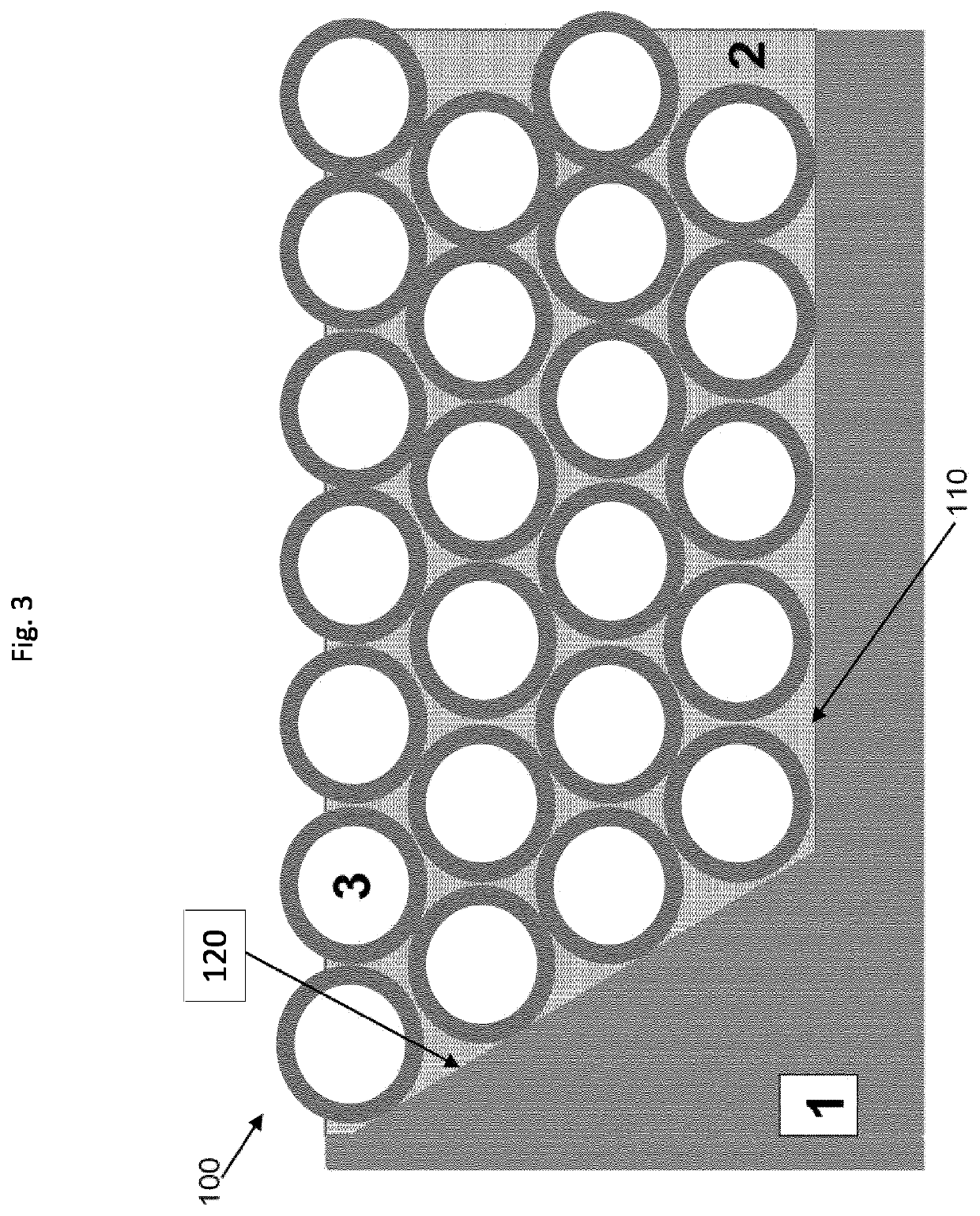
The patent describes a method of arranging pressure vessels in a dry ground depression, which has several advantages. The method can be combined with other steps of construction, machining, and arrangement, and can use machines that operate in dry conditions. Dry arrangement allows for easy connection of pressure vessels to other elements such as pipes, turbines, and pumps. It also allows for larger, more compact arrangements of pressure vessels than if they were sunk afterwards. Using this method is cost-effective and flexible. Additionally, the patent describes a specific approach called "lake-based deployment" which allows for the easy setting down of heavy pressure vessels by filling the ground depression with water in a targeted way.

Problems solved by technology

Due to the inconsistent supply of RE on account of weather and astronomy, and the possibility even of short-term Dunkelflauten [dark doldrums], the energy transition can only be implemented with the use of energy storage systems.
If realized, one would probably have to raise a critical objection that the alternative of almost completely emptying the basins—which would be required for operational reasons—represents an overly brutal landscape intervention and overrides the imperative of reclamation.

Method used


Image

  • Method for Constructing a Pumped Storage Power Plant in a Ground Depression, in Particular in an Open-Cast Mine
  • Method for Constructing a Pumped Storage Power Plant in a Ground Depression, in Particular in an Open-Cast Mine
  • Method for Constructing a Pumped Storage Power Plant in a Ground Depression, in Particular in an Open-Cast Mine

Examples


Embodiment Construction

Expansion of an Existing Open-Pit Mine as a PSPP

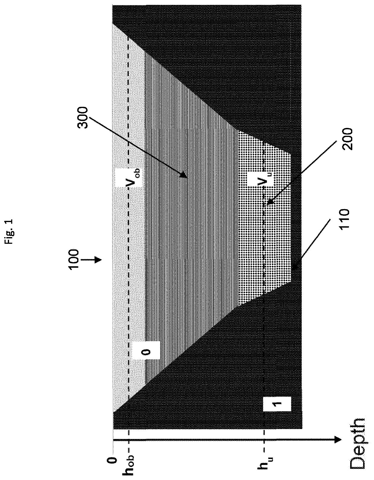
[0132]The following section discusses the expansion of an existing open-pit mine as a PSPP and the particular conditions of a large open-pit mine that is being phased out. However, the statements apply generally to any dry ground depression that already exists or is to be constructed. As will be discussed in more detail below, if the geology is suitable, a PSPP facility can be constructed on a “green field” (or “yellow desert sand”) site without the preparatory work of an open-pit mine being phased out.

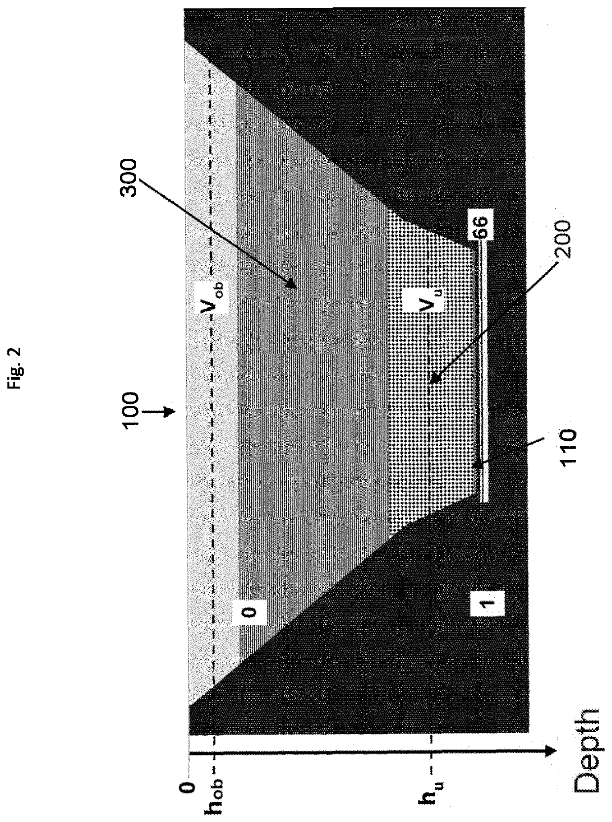
[0133]The following section therefore deals with the approach of optimally and extensively developing an existing open-pit mine for energy storage as an “unconventional PSPP,” using the lake provided by reclamation as the upper basin and a suitable cavity structure to be constructed at the bottom 1 of the lake as the lower basin. This is shown schematically in FIG. 1. The lower basin 200 has the gross volume Vu, but only the portion ther...


PUM


Abstract

The energy transition involves the electrical power supply being almost completely covered by renewable energy sources such as solar plants or wind turbines. However, due to their naturally fluctuating output, these energy sources require the use of large energy storage systems, the realization of which still represents a major problem today. The present invention provides a solution which aims to secure the entire short-term storage capacity needed for the energy transition in Germany (and even Europe). For this purpose, in particular, the invention proposes the construction of a large-scale pumped-storage power plant in the Hambach open-pit mine, as a result of which the can mine be put to subsequent use in a sustainable way. The invention also relates to the construction and partial commissioning of the plant in parallel with the use that is being phased out, in particular that of lignite mining (by 2038). This is to avoid the loss of a significant number of existing jobs. After construction, it is not uncommon for lifetimes of over 100 or even over 1,000 years to be possible, which means that a particular level of sustainability can be ensured.

Description

FIELD OF THE INVENTION[0001]The invention relates to the construction of an underwater pumped-storage power plant in a dry but floodable ground depression, in particular in an abandoned or still operating open-pit mine.[0002]The invention is particularly suitable for the subsequent use of the Hambach open-pit mine or other lignite mining sites and, if realized in the Rhenish mining region, already has the potential to provide the entire short-term storage capacity required in Germany (and possibly even in Europe) after the energy transition. The invention also relates to the construction and partial commissioning of the plant in parallel with the use that is being phased out, in particular that of lignite mining (by 2038). This is to avoid the loss of a significant number of existing jobs.BACKGROUND OF THE INVENTION[0003]The energy transition requires short- and long-term storage systems[0004]The “energy transition” involves almost completely covering the electrical power supply wit...

Claims


Application Information

Patent Timeline
Patent Type & Authority Applications(United States)
IPC IPC(8): F03B13/06
CPCF03B13/06F05B2260/422F05B2260/42F05B2240/40Y02P90/50Y02E10/20Y02E60/16
Inventor SCHMIDT-BÖCKING, HORSTLUTHER, GERHARD
Owner SCHMIDT BOCKING HORST
Learn More