Octogrid constructions and applications utilizing double-double laminate structures

a technology of double-laminated construction and double-laminated structure, which is applied in the direction of machines/engines, transportation and packaging, and other domestic objects, can solve the problems of inability to optimize, inability to use legacy quad composites in those contexts, and issue of minimum gauge, etc., and achieve the effect of optimizing various advantageous characteristics

Active Publication Date: 2022-11-17
THE BOARD OF TRUSTEES OF THE LELAND STANFORD JUNIOR UNIV
View PDF0 Cites 0 Cited by
  • Summary
  • Abstract
  • Description
  • Claims
  • Application Information

AI Technical Summary

Benefits of technology

[0018]It will be shown that, utilizing an octo-grid structure, hub-like components can be constructed from the double-double sub-laminate field and further optimize various advantageous characteristics, achieving unforeseen advantages. These advantages include at least those listed herein-below.
[0020]Also advantageous in the described octo-grid structures is the ability to add shear rigidity with [±45] panel bonded to the opening of the center square grid is also critical in providing a solid foundation for the 8 branches to be joined together. The ability to taper the branches is also simplified, facilitating improvements to reduce the weight without loss of significant stiffness and strength of each branch (see also WO 2020 / 252126). The octogrid can be produced with robotic arms that can place each long and short strips in prescribed order, with minimized manual labor, which may be error-prone and the like. Still further, as non-limiting examples, hubs for propellers and wind turbine blades or the like can also be replaced by octogrid, with extended branches to serve as spars. Significant weight and cost reductions are possible with spars the go through the center of the joints. The branches of octogrid can be [0] or double-double to provide a balance between bending and twisting.
[0021]Various embodiments of the present invention are thus directed toward an octogrid sub-structure for use in forming a composite laminate structure. The octogrid sub-structure comprises: a first ply layer comprising a plurality of first elongate tapes oriented in a first direction and a plurality of second elongate tapes oriented in a second direction, the second direction being offset from the first direction at an approximate right angle; and a second ply layer comprising a plurality of third elongate tapes oriented in the first direction and a plurality of fourth elongate tapes oriented in the second direction, the second ply layer being overlaid atop the first ply layer, wherein: each of the plurality of first, second, third and fourth elongate tapes comprises a first set of ply layers and a second set of ply layers offset from the first set of ply layers by an angle of at least 25 degrees; a first end of each of the plurality of first, second, third and fourth elongate tapes is positioned approximately adjacent a midpoint of an adjacently positioned one of the plurality of first, second, third and fourth elongate tapes; and a second and opposing end of each of the plurality of first, second, third and fourth elongate tapes extends freely beyond a central grid portion defined by a length of a portion between the first end and the midpoint of a portion of the plurality of first, second, third and fourth elongate tapes.
[0022]Various embodiments of the present invention are also directed toward a composite octogrid structure for use in a composite laminate structure. This structure comprises: a plurality of first ply layers each comprising a plurality of first elongate tapes oriented in a first direction and a plurality of second elongate tapes oriented in a second direction, the second direction being offset from the first direction at an approximate right angle; and a plurality of second ply layers each comprising a plurality of third elongate tapes oriented in the first direction and a plurality of fourth elongate tapes oriented in the second direction, wherein: the plurality of first and second ply layers are overlaid relative to one another in an alternating fashion so that a first ply layer is intermediate any sequential second ply layers and vice-versa; each of the plurality of first, second, third and fourth elongate tapes comprises a first set of ply layers and a second set of ply layers offset from the first set of ply layers by an angle of at least 25 degrees; a first end of each of the plurality of first, second, third and fourth elongate tapes is positioned approximately adjacent a midpoint of an adjacently positioned one of the plurality of first, second, third and fourth elongate tapes; a second and opposing end of each of the plurality of first, second, third and fourth elongate tapes extends freely beyond a central grid portion defined by a length of a portion between the first end and the midpoint of a portion of the plurality of first, second, third and fourth elongate tapes.
[0023]Various embodiments of the present invention are still further directed toward a method of forming a composite octogrid laminate structure. The method involves: forming a plurality of first ply layers by sequentially dispensing a plurality of first elongate tapes oriented in a first direction and a plurality of second elongate tapes oriented in a second direction, the second direction being offset from the first direction; forming a plurality of second ply layers by sequentially dispensing a plurality of third elongate tapes oriented in the first direction and a plurality of fourth elongate tapes oriented in the second direction; and stacking the plurality of first and second ply layers in an alternating fashion so that a first ply layer is intermediate any sequentially stacked second ply layer and vice-versa, wherein: each of the plurality of first, second, third and fourth elongate tapes comprises a first set of ply layers and a second set of ply layers offset from the first set of ply layers by an angle of at least 25 degrees; a first end of each of the plurality of first, second, third and fourth elongate tapes is positioned approximately adjacent a midpoint of an adjacently positioned one of the plurality of first, second, third and fourth elongate tapes; a second and opposing end of each of the plurality of first, second, third and fourth elongate tapes extends freely beyond a central grid portion defined by a length of a portion between the first end and the midpoint of a portion of the plurality of first, second, third and fourth elongate tapes.

Problems solved by technology

The above is a unique issue with the legacy quad family of laminates.
But such arbitrarily added plies, in thickness less than 6, 8, or 10 plies, differ from the properties of the sub-laminates and make optimization practically impossible.
There is also an issue on minimum gauge.
The use of legacy quad composites is thus not feasible in those contexts, such as for example in the realm of fuselage or wing skins.
Sub-laminates of this nature were also delamination prone, and multiple failure modes resulting from thousands of fiber discontinuities and matrix cracking.
Complex procedures to blend adjacent laminates with different stacking and thickness, and to drop or add plies are required for a complex structure and impede optimization and manufacturing.
Notably, though, holes remain visible between the respective discrete sub-laminate structures (i.e., although some of the dots or anchors 6 may partially overlap one another, not all of the dots or anchors 6 fully overlap with each other and thus fill all of the visible space in the field); as a result, achieving certain desirable material characteristics remains challenging and many times simply unachievable (again, due to the various self-inflicted constraints on conventional legacy quad field sub-laminates having different thicknesses in 6 to 10-plies that make blending and ply drop so complicated).
Inefficiencies arose in conventional composite laminate structures due to their discrete nature, exacerbated by self-inflicted constraints in the industry, including a perceived requirement that all composite laminate structures—and in particular the sub-laminate structures therein—have balanced and symmetric material characteristics; stated otherwise, they involve necessarily thick sub-laminate structures and mid-plane symmetry.
Such constraints have historically largely remained unchallenged due to concerns that conventional composite laminated structures will undesirably warp upon cool down from a curing temperature or increased residual stress when the operating temperature changes.
Such lamination processes are generally time and labor intensive as well as being prone to error, requiring special attention to ensure precision ordering of the respective composite layers and may result in an unnecessary number of plies, which may contribute to excessive process waste and cost.
Still further symmetric laminates have historically proven cumbersome when seeking to taper the exterior surface of a structure, due at least in part to the desire to maintain symmetry throughout, even when dropping ply layers to form the taper.
Balanced and symmetric laminates of this nature have also traditionally created difficulty when trying to minimize laminate and even sub-laminate thickness, requiring ever thinner plies as the only option to offset the need to add 6-, 8- or 10-ply (or even more plies such as being doubled when symmetry is required) to achieve desirable material characteristics.
Tapering (i.e., ply drop) complexities have also existed in these structures as well, with one exemplary limitation being that dropping of specific plies or groups thereof must not disturb the desired symmetry and balance.
As a result, due to the discrete nature of available ply angles (influenced by both the extra thick sub-laminate structures and the symmetry constraints detailed herein), there were necessarily gaps between achievable laminate stiffness and / or strength characteristics that simply could not be bridged.
Multiple failure modes, thousands of fiber discontinuities from ply drops and results from blending, and complexity in manufacturing were thus often faced due to self-inflicted constraints; stated otherwise, an optimal set of material characteristics in a laminate structure oftentimes had to be sacrificed to satisfy various self-imposed constraints; as a result, less than optimal laminate structures were used.
For example, in certain circumstances, joints are the weakest points, shear rigidity is minimal, tapering is cumbersome, and hub construction (i.e., for propellers and / or blades) are inefficient with respect to weight and / or labor.

Method used


Image

  • Octogrid constructions and applications utilizing double-double laminate structures
  • Octogrid constructions and applications utilizing double-double laminate structures
  • Octogrid constructions and applications utilizing double-double laminate structures

Examples


Embodiment Construction

[0046]The present invention now will be described more fully hereinafter with reference to the accompanying drawings, in which some, but not all embodiments of the invention are shown. Indeed, this invention may be embodied in many different forms and should not be construed as limited to the embodiments set forth herein; rather, these embodiments are provided so that this disclosure will satisfy applicable legal requirements. Like numbers refer to like elements throughout.

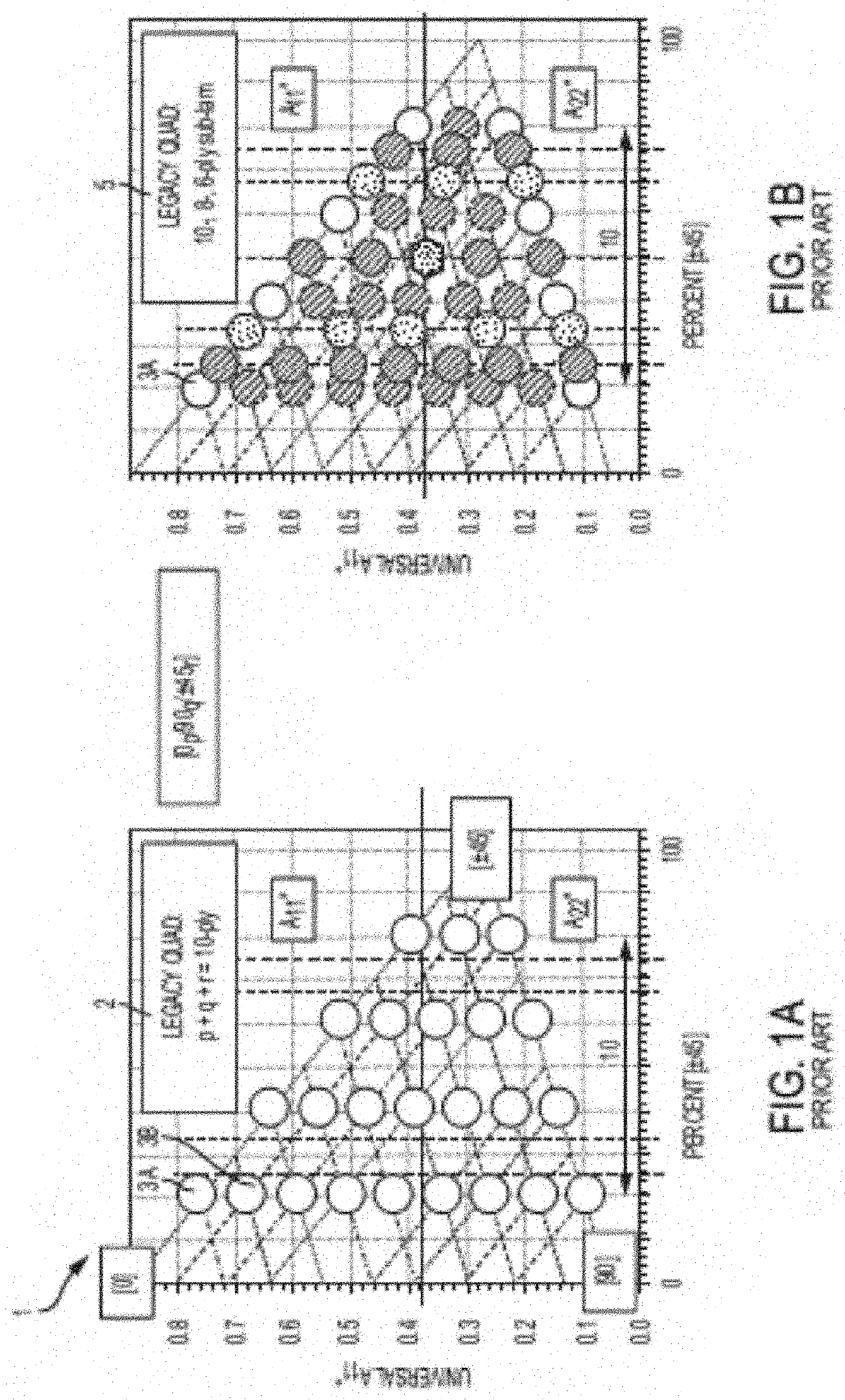
[0047]Conventional Laminate Characteristics

[0048]As mentioned previously herein, conventional legacy quad laminates were made of collections of [0], [±45] and [90] ply configurations. These laminates were discrete and not possible to interpolate due to a variety of self-inflicted constraints (e.g., fixed angles, symmetry, etc.). To have more directional properties, plies had to be added to their sub-laminates, which in turn increased weight and decreased design flexibility of laminate structures due to thickness. ...


PUM

PropertyMeasurementUnit
angleaaaaaaaaaa
angleaaaaaaaaaa
angleaaaaaaaaaa

Abstract

An octogrid structure and method of forming the same for a composite laminate structure is provided. The octogrid sub-structure comprises: a first ply layer comprising a plurality of first elongate tapes oriented in a first direction and a plurality of second elongate tapes oriented in a second direction; and a second ply layer comprising a plurality of third elongate tapes oriented in the first direction and a plurality of fourth elongate tapes oriented in the second direction, the second ply layer being overlaid atop the first ply layer. A first end of each of the elongate tapes is positioned approximately adjacent a midpoint of an adjacently positioned one of the elongate tapes; and a second and opposing end of each of elongate tapes extends freely beyond a central grid portion defined by a length of a portion between the first end and the midpoint of the elongate tapes.

Description

CROSS REFERENCE TO RELATED APPLICATIONS[0001]This application claims priority to and the benefit of U.S. Provisional Application No. 63 / 188,206, filed May 13, 2021; the contents of which as are hereby incorporated by reference in their entirety.BACKGROUNDTechnical Field[0002]The present invention relates generally to certain applications of composite laminates and / or utilization of the composite laminates formed from double-double laminate configurations and constructed into octogrid structures having various applications, including without limitation with drones (e.g., unmanned aircraft) and / or wind turbines. Octogrid structures may be lighter, stronger, and lower in cost, as compared to conventional laminate structures, due in part to ease of tapering, finite-length pre-cut tapes, and the like.Description of Related Art[0003]Conventional composite laminate structures were generally designed to emulate the strength characteristics of conventional metal-based laminate materials and ...

Claims


Application Information

Patent Timeline
Patent Type & Authority Applications(United States)
IPC IPC(8): B29C70/30F03D1/06B64C11/26
CPCB29C70/304F03D1/0675B64C11/26B29K2995/0094B29L2031/085B29D99/0028B64C2001/0072B29C70/386B29C70/22F05B2230/60B32B3/14
Inventor TSAI, STEPHEN W.ZHENG, CHUANXIANGROY, SURAJIT
Owner THE BOARD OF TRUSTEES OF THE LELAND STANFORD JUNIOR UNIV
Why Eureka
Try Eureka