Method for dispersing and milling particles in a fluid

a technology of fluid and particle dispersing, which is applied in the direction of mixing, transportation and packaging, rotary stirring mixers, etc., can solve the problems of difficult dispersing and milling of particles in fluid, and achieve the effect of evenly milling particles

Pending Publication Date: 2022-11-17
BASF COATINGS GMBH
View PDF0 Cites 0 Cited by
  • Summary
  • Abstract
  • Description
  • Claims
  • Application Information

AI Technical Summary

Benefits of technology

[0005]It is an object of the present invention to provide a method and a system for dispersing particles in a fluid that allow to reduce the production time and energy for products pro-duced in a recirculation process.
[0007]Since the retrieving position for retrieving the fluid from the stirring container to be passed through the mill is determined such that the retrieved fluid comprises particles with an average particle size differing from the average particle size of particles in the fluid in the mixing region as defined by the stirring means, it can be assured that fluid comprising particles that have not passed the mill often enough, i.e. the size of which is still too large, is sent to the mill, whereas the amount of particles in the retrieved fluid that already have been milled during a previous pass is reduced. Accordingly, the size of the particles can be reduced more effectively, i.e. in each pass more particles of a larger size are sent through the mill than particles having already a smaller size. Thus, the number of passes necessary for reaching a predetermined average particle size can be reduced, which leads to a re-duction of the production time and energy for producing a given final product.
[0009]From there, the mixed fluid will slowly be transported to other parts of the stirring container. Accordingly, if the fluids mixed in the stirring container comprise particles with different sizes, for instance, when the fluid within the container comprises particles of a first particle size and the fluid introduced in the stirring container comprises particles of a second particle size, wherein the first particle size is larger than the second particle size, the particles of different sizes will also only be mixed in the mixing region. Thus, firstly, the average size of the particles is reduced in the mixing region, whereas in all other regions of the container the average particle size is only reduced very slowly together with the transport of the mixed fluid into other regions of the stirring container. The inventors have realized that this mixing phenomenon comprising different internal streams can be used as an advantage for a more effective method and system for recirculating a fluid comprising particles the size of which should be reduced by letting the fluid pass through a mill during a recirculation process. Retrieving the fluid comprising the particles from a region of the container outside the mixing region ensures that the amount of particles in the retrieved fluid that still have to be milled at least once is maximized. Thus, the milling of the particles will be more effective and the production time of the final product comprising a predetermined average particle size is reduced.
[0023]In an embodiment, the reintroduction position is provided above the stirring position. Preferably, the reintroduction position is provided in an upper half of the container, preferably at or over the surface of the fluid in the stirring container. Preferably the reintroduction position is provided above the surface of the fluid within the stirring container such that the fluid is reintroduced in the direction of an inner wall of the stirring container. This configuration allows to reduce the risk of static electric charge build up.
[0024]In an embodiment, the stirring position is provided within an upper half of the stirring container and the retrieving position is provided in a lower half of the stirring container. Experiments and simulations have shown that if the stirring position is in an upper half of the stirring container, the mixing of the reintroduced fluid and the fluid within the container takes place mainly in the upper half of the container. Accordingly, particles that have not passed the mill already or as often as others can mainly be found in the lower half of the stirring container. Thus, the average particle size in the lower half of the stirring container remains higher than in the upper half of the stirring container during the recirculation process. It is therefore advantageous to provide a retrieving position in the lower half of the stirring container for this configuration. Preferably, this embodiment is used in applications comprising fluids with a high viscosity that might cause difficulties when pumped. In such cases the retrieving position at the bottom can facilitate the pumping of the fluid.
[0025]Alternatively, in an embodiment the stirring position is provided within a lower half of the stirring container and the retrieving position is provided in an upper half of the stirring container. If the stirring position is provided within a lower half of the stirring container, it has been found through experiment and simulation that the mixing between the reintroduced fluid and the fluid within the container takes place mainly within the lower half of the stirring container, although the fluid is reintroduced in the upper half of the container. Accordingly, it is advantageous to provide the retrieving position in the upper half of the stirring container. In a preferred modification of this embodiment, an additional retrieving means are provided at the bottom of the stirring container, wherein the retrieving means and the additional retrieving means are connected and wherein the additional retrieving means comprises fluid regulation means, like a valve or a volumetric pump with a speed variator, for regulating the retrieving of fluid with the additional retrieving means. Preferably, the fluid regulation means are adapted to regulate the flow such that the flow through the additional retrieving means is increased when it is determined that the effort for pumping is increased, for instance, if cavitation noise from a pump pumping the fluid through the retrieving means is detected. This embodiment is especially advantageous for saving energy for operating the pump.

Problems solved by technology

Dispersing and milling particles evenly in a fluid can be very difficult.

Method used


Image

  • Method for dispersing and milling particles in a fluid
  • Method for dispersing and milling particles in a fluid
  • Method for dispersing and milling particles in a fluid

Examples


Embodiment Construction

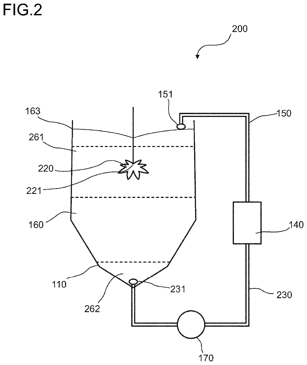
[0039]FIG. 1 shows schematically and exemplarily an embodiment of a system for dispersing and milling particles in a fluid by recirculation. In this embodiment, the system 100 comprises a stirring container 110 into which a fluid 160 comprising particles 164 can be introduced. Stirring means 120 are provided at a stirring position 121 within the stirring container 110. In this exemplary embodiment, the stirring position 121 is provided within a lower half of the stirring container 110. In this embodiment, the stirring means 120 comprise an impeller, wherein the impeller is rotated and causes turbulent fluid flows in the vicinity of the impeller. In this embodiment, the impeller is a Cowsle disk. In a preferred embodiment the impeller is rotated with a rotation speed of 2 to 3 times the rotational speed used for dispersing the particles before the recirculating and milling is started. Preferably, the speed of the impeller is regulated such that a vortex is generated in the stirring c...


PUM

PropertyMeasurementUnit
particle sizeaaaaaaaaaa
sizeaaaaaaaaaa
timeaaaaaaaaaa

Abstract

Described herein is a method and a system for dispersing particles in a fluid. The method includes stirring a fluid including particles in a stirring container using stirring means. During stirring the fluid is recirculated by continuously retrieving an amount of fluid from a retrieving position. Further, the particles are milled, where during each pass through the milling means a size of particles in the retrieved fluid is reduced. The retrieved fluid having passed through the milling means is continuously reintroduced into the stirring container at a reintroduction position. The reintroduced fluid is mixed with the fluid in the stirring container in a mixing region defined by the stirring means, and the retrieving position is determined such that the retrieved fluid includes particles with an average particle size differing from the average particle size of particles in the mixing region.

Description

FIELD OF THE INVENTION[0001]The invention relates to a method and an optimized system for dispersing and milling particles by recirculation in a fluid.BACKGROUND OF THE INVENTION[0002]Dispersing and milling particles evenly in a fluid can be very difficult. In many applications it is necessary to reduce the size of particles and agglomerates that are dispersed in a fluid by milling, for instance, during the production of paint using a liquid binder and particles of a coloured pigment. One solution for dispersing particles in a fluid, for instance, colour pigment in a binder, while further reducing the size of the particles, is to provide a recirculation through a bead mill, in which the fluid with the particles is continuously stirred in a stirring container, like a vessel, mixing tank, stirring tank, homogenizer, etc., and at the same time recirculated through a mill that reduces the size of the particles with each pass through the mill until a desired particle size and the targete...

Claims


Application Information

Patent Timeline
Patent Type & Authority Applications(United States)
IPC IPC(8): B01F25/52B01F23/53B01F27/91B01F35/221
CPCB01F25/52B01F23/53B01F27/91B01F35/2211B01F2101/30
Inventor ROBERT, FABIENBENOIST, BERNARDPAVEN, STEPHANE
Owner BASF COATINGS GMBH
Why Eureka
Try Eureka