Catalytic reactor system and catalyst for conversion of captured c02 and renewable h2 into low-carbon syngas

a catalyst and catalytic reactor technology, applied in physical/chemical process catalysts, metal/metal-oxide/metal-hydroxide catalysts, separation processes, etc., can solve the problem of catalyst not meeting cosub>2, difficult to manufacture multiple ton quantities of catalyst, and not known if can be used commercially in traditional catalytic reactors

Pending Publication Date: 2022-11-03
INFINIUM TECH LLC
View PDF0 Cites 2 Cited by
  • Summary
  • Abstract
  • Description
  • Claims
  • Application Information

AI Technical Summary

Benefits of technology

[0016]The catalytic reactor described in this document has been improved by adding an insulating, non-reactive surface to the interior catalyst walls which do not react with the syngas and effect catalyst performance. Other catalytic reactor systems and configurations are described that work with the RWGS catalyst.

Problems solved by technology

It would be difficult to manufacture this catalyst in multiple ton quantities (criteria #2) and it is not known if can be used commercially in traditional catalytic reactors (criteria #5 and #6).
This catalyst does not meet CO2 to CO conversion efficiency requirements (criteria #8) and CO production selectivity (criteria #9).
However, copper containing catalysts tend to deactivate over time by sintering at high temperatures.
In conclusion, none of the catalysts described in the art meet even half of the quality and performance requirements for the effective, commercial conversion of H2 / CO mixtures to syngas.

Method used


Image

  • Catalytic reactor system and catalyst for conversion of captured c02 and renewable h2 into low-carbon syngas
  • Catalytic reactor system and catalyst for conversion of captured c02 and renewable h2 into low-carbon syngas

Examples


example

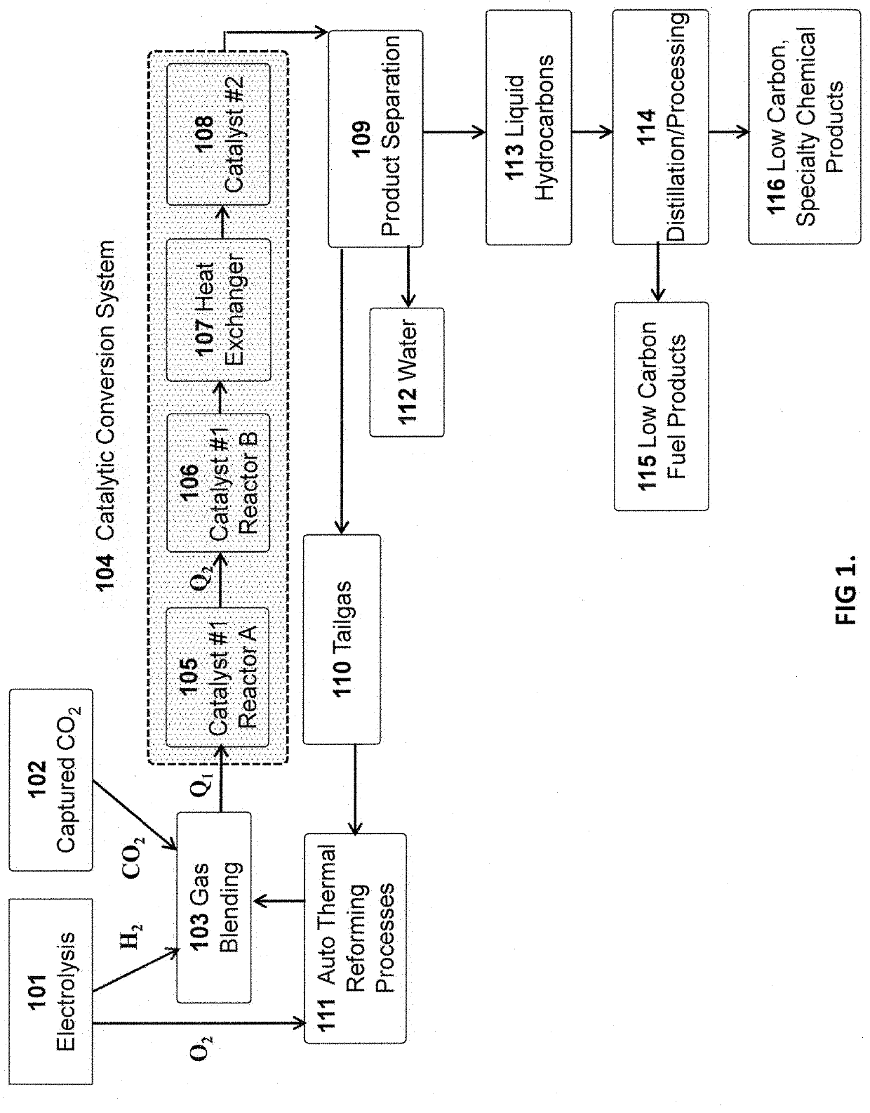
[0035]The following are examples for the conversion of H2 and CO2 mixtures to syngas using various catalytic conversion system designs and operational specifications.

[0036]Example #1—In this example, catalytic Reactors A 105 and Reactor B 106 are identical in size and operated under the same conditions of pressure, temperature and space velocity. The H2 / CO2 blend (3.4 / 1.0 v / v) is heated to 1,650° F., compressed to 300 psi and fed into catalytic reactor A 105 at a space velocity of about 17,000 hr−1.

[0037]Since the catalytic conversion of the H2 / CO2 mixture syngas is endothermic, the temperature of the gas reactants and products are decreased, and the CO2 conversion efficiency is reduced as the gas passes through the reactor. FIG. 1 illustrates the relationship between CO2 conversion efficiency and gas temperature. The CO2 conversion efficiency at the inlet of the catalyst bed is 82% with a CO production selectivity greater than 99%.

[0038]The exit temperature of the unreacted and pro...


PUM

PropertyMeasurementUnit
pressureaaaaaaaaaa
volume percentaaaaaaaaaa

Abstract

The present invention describes an improved catalytic reactor system with an improved catalyst that transforms CO2 and low carbon H2 into low-carbon syngas with greater than an 80% CO2 conversion efficiency, resulting in the reduction of plant capital and operating costs compared to processes described in the current art. The inside surface of the adiabatic catalytic reactors is lined with an insulating, non-reactive surface which does not react with the syngas and effect catalyst performance. The improved catalyst is robust, has a high CO2 conversion efficiency, and exhibits little or no degradation in performance over long periods of operation. The low-carbon syngas is used to produce low-carbon fuels (e.g., diesel fuel, jet fuel, gasoline, kerosene, others), chemicals, and other products resulting in a significant reduction in greenhouse gas emissions compared to fossil fuel derived products.

Description

FIELD OF THE INVENTION[0001]The present invention describes an improved catalytic reactor system, which may include single or tandem reactors, with an improved catalyst that transforms captured CO2 and renewable H2 into low-carbon syngas with greater than an 80% CO2 conversion efficiency. The improved catalyst is robust, has a high CO2 conversion efficiency, and exhibits little or no degradation in performance over long periods of operation. The low-carbon syngas is used to produce low-carbon fuels (e.g., diesel fuel, jet fuel, gasoline, kerosene, others), chemicals (methanol, alcohols, olefins, solvents, others), and other products resulting in a significant reduction in greenhouse gas emissions, compared to fossil fuel derived products.BACKGROUND OF THE INVENTION[0002]Carbon dioxide is produced by many industrial and biological processes. Carbon dioxide is usually discharged into the atmosphere. However, since carbon dioxide has been identified as a significant greenhouse gas, the...

Claims


Application Information

Patent Timeline
Patent Type & Authority Applications(United States)
IPC IPC(8): C01B32/40C01B3/40B01J8/04B01J21/04
CPCC01B32/40C01B3/40B01J8/04B01J21/04C01B2203/0233C01B2203/0283C01B2203/085C01B2203/1628C01B2203/1614B01J2208/00477B01J35/023B01J35/1014B01J23/005B01J21/10B01J23/80B01J23/74B01D53/8693B01J8/001B01J8/02B01J8/065B01J2208/00176B01J2208/0053B01J2208/00805B01J2208/027B01D2257/504C01B3/12C25B1/04C01B2203/062C25B15/081C25B15/00
Inventor SCHUETZLE, DENNISSCHUETZLE, ROBERTHANBURY, ORIONCALDWELL, MATTHEWMCGINNIS, GLENNRODRIGUEZ, RAMER
Owner INFINIUM TECH LLC
Why Eureka
Try Eureka