
Image display apparatus, information display system for vehicle, and optical film

a technology of information display system and image display apparatus, which is applied in the direction of identification means, instruments, polarising elements, etc., can solve the problems of mounting combination, high manufacturing cost, and difficulty in achieving both the display of clear image to the driver and the reduction of reflected glare on the window glass

Pending Publication Date: 2022-10-13
FUJIFILM CORP
View PDF0 Cites 0 Cited by
  • Summary
  • Abstract
  • Description
  • Claims
  • Application Information

AI Technical Summary

Benefits of technology

The technical effect of this patent is to provide a low-cost image display apparatus that can display a clear image to the driver while reducing reflected glare on the window glass. The apparatus has asymmetry in display characteristics and is thinly made while causing no moire. Additionally, an information display system for a vehicle and an optical film can also be provided.

Problems solved by technology

However, conventional louver films have symmetry horizontally or vertically, and it is difficult to achieve both the display of a clear image to the driver and the reduction of reflected glare on the window glass.
When a louver film is combined with an electro-optical element that controls the viewing angle, the visible range (observation direction in which the image on the display can he seen) can he controlled relatively freely; however, the thickness of the device increases so that it is difficult to mount the combination in the limited space inside a vehicle, and the manufacturing cost also increases high.

Method used


Image

  • Image display apparatus, information display system for vehicle, and optical film
  • Image display apparatus, information display system for vehicle, and optical film
  • Image display apparatus, information display system for vehicle, and optical film

Examples


example 1-1

[0479](Production of Temporary Support)

[0480]A triacetyl cellulose film (TAC film) having a thickness of 60 μm manufactured by FUJIFILM Corporation was prepared. On the other hand, the following alignment film coating liquid was prepared, heated and dissolved at 85° C. for one hour with stirring, and filtered through a 0.45-μm filter.

[0481]Alignment Film Coating Liquid

PVA203 (polyvinyl alcohol  2.4 parts by massmanufactured by Kuraray Co., Ltd.)Pure water 97.6 parts by mass

[0482]The prepared alignment film coating liquid was applied on the TAC film while regulating the coating amount so that the film thickness after drying would be 0.5 μm, and the alignment film coating liquid was dried at 100° C. for 2 minutes.

[0483]The dried coating film was subjected to a rubbing treatment to produce a film-like temporary support. The direction of the rubbing treatment was set to be parallel to the longitudinal direction of the film.

[0484]It was confirmed that as the temporary support, a general ...

example 1-2

[0508]A transfer film Z2 was produced in the same manner as in Example I-1, except that during the formation of the liquid crystal layer, the thickness of the liquid crystal layer was set to 1.1 μm, the liquid crystal layer X2 was formed without performing nitrogen purging at the time of performing ultraviolet exposure, and during the formation of the liquid crystal cured layer, the thickness of the liquid crystal cured layer was set to 1.5 μm, and the liquid crystal cured layer Y2 was formed without performing nitrogen purging at the time of performing ultraviolet exposure, and an optical film was produced by using this as an optically anisotropic layer. That is, the optical film of Example 1-2 was made to have a support, an alignment film, a liquid crystal layer X2, a liquid crystal cured layer Y2, and a polarizer. In Example 1-2, it can be said that the liquid crystal layer X2 is a liquid crystal cured layer included in the optically anisotropic layer.

[0509](Measurement of Tilt A...

example 2-1

[0566]An optical film was produced in the same manner as in Example 1-1.

[0567](Production of Image Display Apparatus)

[0568]The produced optical film was mounted on a display as follows to produce an image display apparatus having the configuration shown in FIG. 42.

[0569]A notebook PC (personal computer) manufactured by Lenovo Group, Ltd., ThinkPad T490s, was used for the display, and the liquid crystal display element portion was disassembled to take out the liquid crystal display panel. At that time, the directions of the absorption axes of the polarizing plates disposed on both sides of the liquid crystal cell of ThinkPad T490s were checked. It was confirmed that the absorption axis of the viewing-side polarizing plate was in the horizontal direction, and the absorption axis of the backlight-side polarizing plate was in the vertical direction. Subsequently, the optical film was bonded and mounted on the viewing-side polarizing plate. At that time, the absorption axis of the polari...


PUM

PropertyMeasurementUnit
Fractionaaaaaaaaaa
Angleaaaaaaaaaa
Angleaaaaaaaaaa

Abstract

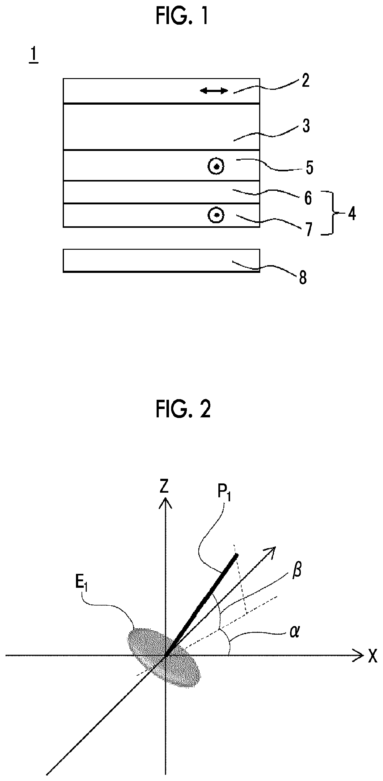
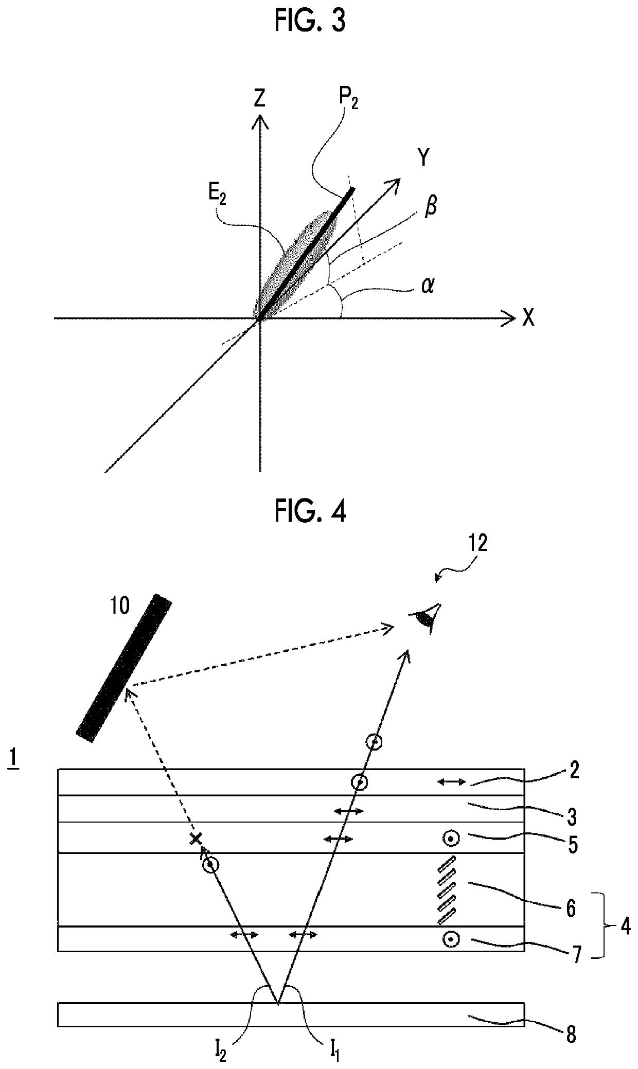
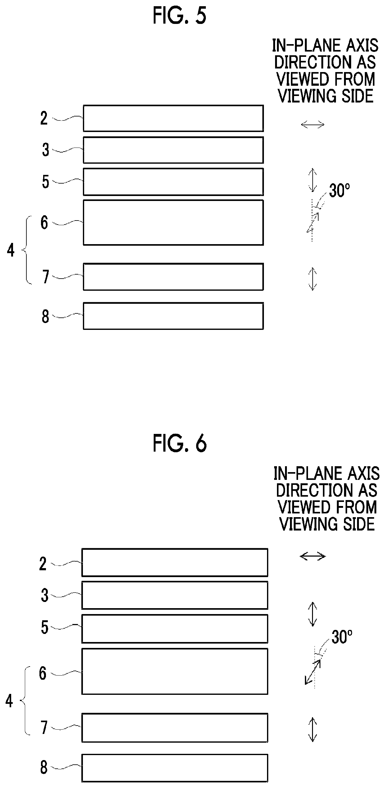
Provided is a low-cost image display apparatus that has asymmetry in the display characteristics in the right-to-left direction, displays a clear image to the driver, exhibits an appropriate viewing angle control function that reduces reflected glare on the window glass, and is thinly made While causing no moire, and there are also provided an information display system for a vehicle, and an optical film. The image display apparatus includes a viewing-side polarizing plate, a liquid crystal cell, a backlight-side polarizing plate, an optical film, and a backlight in this order, in which the optical film includes an optically anisotropic layer and a polarizer in this order from the liquid crystal cell side, the absorption axis of the backlight-side polarizing plate and the absorption axis of the polarizer are parallel or orthogonal to each other, the optically anisotropic layer is optically uniaxially anisotropic, while in a case where the optic axis of the optically anisotropic layer is projected onto the polarizer as viewed from the viewing-side of the image display apparatus, the azimuthal angle of the optic axis is +50° to +70° or −50° to −70° with respect to the horizontal direction, the average tilt angle of the optic axis with respect to the main surface of the optically anisotropic layer is 20° to 45°, and the in-plane phase difference Re (550) of the optically anisotropic layer is 70 nm to 240 nm.

Description

CROSS-REFERENCE TO RELATED APPLICATIONS[0001]This application is a Continuation of PCI International Application No. PCT / JP2020 / 044247 filed on Nov. 27, 2020, which claims priority under 35 U.S.C. § 119(a) to Japanese Patent Application No. 2019-238746 filed on Dec. 27, 2019 and Japanese Patent Application No. 2020-139926 filed on Aug. 21, 2020. Each of the above applications is hereby expressly incorporated by reference, in its entirety, into the present application.BACKGROUND OF THE INVENTION1. Field of the Invention[0002]The present invention relates to an image display apparatus, an information display system for a vehicle equipped with the image display apparatus, and an optical film used in this image display apparatus.2. Description of the Related Art[0003]Image display apparatuses are required to have a wide viewing angle in use applications such as televisions, monitors, and mobile devices. Particularly, a liquid crystal display device is optically compensated by using a re...

Claims


Application Information

Patent Timeline
IPC IPC(8): G02B5/30C09K19/56C09K19/38B60K35/00
CPCG02B5/3016C09K19/56C09K19/3852B60K35/00B60K2370/152B60K2370/18B60K2370/23B60K2370/37B60K2370/33G09F9/30G02F1/1335C09K2019/0448C09K19/3486C09K19/542B60K35/22B60K2360/1523B60K2360/25B60K35/415C09K2323/03C09K2323/00B60K35/29B60K2360/18B60K2360/23B60K2360/33
Inventor YOSHINARI, SHINICHIFUJIWARA, ISAO
Owner FUJIFILM CORP
Learn More