
Surgery 3D Visualization Apparatus

Active Publication Date: 2022-10-13
RAYTRX LLC
View PDF10 Cites 0 Cited by
  • Summary
  • Abstract
  • Description
  • Claims
  • Application Information

AI Technical Summary

Benefits of technology

The invention is a compact and maneuverable apparatus that can be used in surgery or for eye examination in different patient positions. The system can capture 2D or 3D imaging without any flaws on the patient's cornea or iris. The apparatus allows for conventional or coaxial illumination. The technical effects of this invention are improved imaging quality and versatility in patient positioning and illumination.

Problems solved by technology

In many cases, digital image acquisition and visualization tools have been added to legacy systems that were designed for use with analog and some earlier electronic visualization tools, limiting the abilities of full digital applications.
Such earlier systems provide some level of advancement, but often suffer from poor ergonomics and are not readily modified or adaptable for taking better advantage of digital processing and display capabilities.
Systems especially useful for ophthalmology present a particular challenge, due to factors including complexity of the optical path, space constraints, difficulties related to brightness, and disappointing resolution.
With problems such as low patient tolerance to bright light and the often-poor quality of the viewed image, indirect ophthalmoscopy remains a difficult procedure that can be inaccurate and may degrade the overall quality of retinal examination.
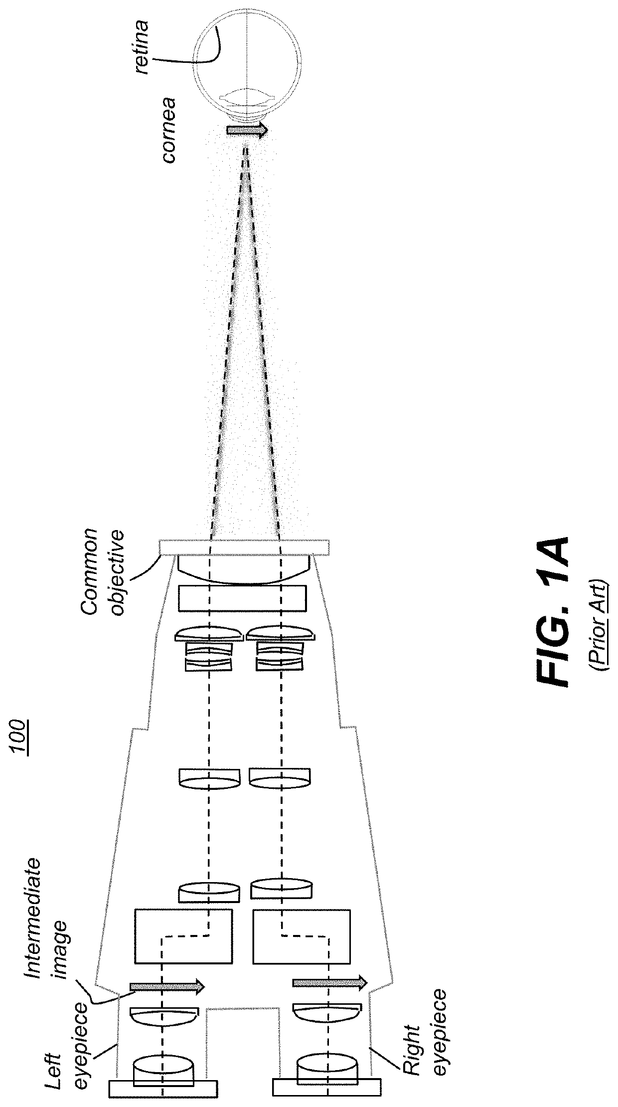
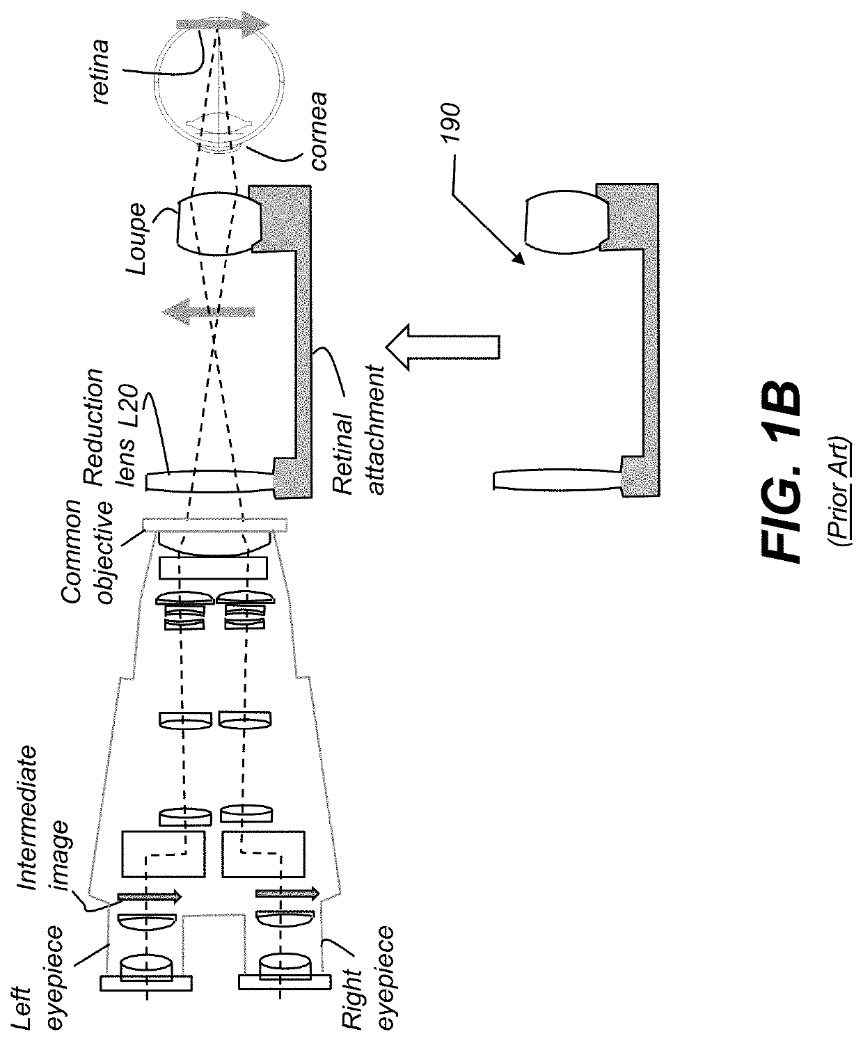
Particular challenges for this device include the following:(i) need to image all portions of the eye in 3D, for both the cornea and the retina;(ii) need to switch easily from anterior to posterior imaging;(iii) need for systems where the components close to the patients are can be easily and expediently sterilized to reduce operation time and cost;(iv) requirements for patient safety during operation;(v) need for improved surgeon ergonomics;(vi) poor visibility of various features within the eye due to the limited aperture sizes of the 3D apertures;(vii) need for higher resolution for detection;(viii) need for wide angle visibility of the retina;(ix) image rectification;(x) need to reduce microscope size to reduce patient obscuration and to allow maneuverability of the microscope for orientation at different viewing angles;(xi) need to be able to readily switch from lower resolution 3D mode to a high-resolution monoscopic or mesoscopic viewing-mode;(xii) need to be able to use both in intra-vitreous illumination as well as external illumination.

Method used


Image

  • Surgery 3D Visualization Apparatus
  • Surgery 3D Visualization Apparatus
  • Surgery 3D Visualization Apparatus

Examples


Embodiment Construction

[0061]The following is a detailed description of the preferred embodiments of the disclosure, reference being made to the drawings in which the same reference numerals identify the same elements of structure in each of the several figures.

[0062]Where they are used, the terms “first”, “second”, and so on, do not necessarily denote any ordinal, sequential, or priority relation, but are simply used to more clearly distinguish one element or set of elements from another, unless specified otherwise.

[0063]While the devices and methods have been described with a certain degree of particularity, it is to be noted that many modifications may be made in the details of the construction and the arrangement of the devices and components without departing from the spirit and scope of this disclosure. It is understood that the devices and methods are not limited to the embodiments set forth herein for purposes of exemplification. It will be apparent to one having ordinary skill in the art that the...


PUM


Abstract

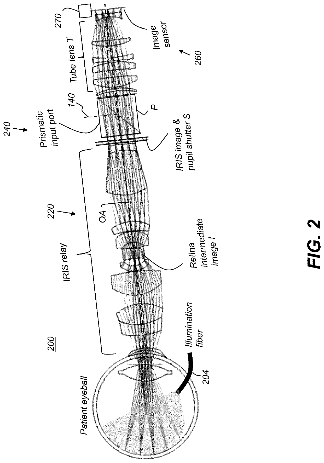
An apparatus for obtaining an image of a retina has an optical relay that defines an optical path and is configured to relay an image of the iris along the optical path to a pupil; a shutter disposed at the pupil and configured to define at least a first shutter aperture for control of light transmission through the pupil position; a tube lens disposed to direct light from the shutter aperture to an image sensor; and a prismatic input port disposed between the shutter and the tube lens and configured to combine, onto the optical path, light from the relay with light conveyed along a second light path that is orthogonal to the optical path.

Description

CROSS REFERENCE TO RELATED APPLICATIONS[0001]This application claims the benefit of U.S. Provisional Application Ser. 63 / 168,353, entitled “SURGERY 3D VISUALIZATION APPARATUS”, in the names of David Kessler, Ph.D., Michael H. Freeman, J. D., et al., filed on 31 Mar. 2021 and incorporated herein in its entirety.FIELD OF THE DISCLOSURE[0002]The present disclosure generally relates to optical apparatus for clinical and surgical use and more particularly to a system for acquisition and display in ophthalmology for visualization of patient retina and cornea under examination and treatment.BACKGROUND[0003]Continuing advances in medical treatment have been provided using improved systems for visualization, helping to support the medical practitioner with advanced functions and features that employ aspects of digital image acquisition, processing, and display. Handling image content in digital form, in turn, allows advanced surgical support systems to provide automated functions that includ...

Claims


Application Information

Patent Timeline
IPC IPC(8): A61B3/14A61B90/00H04N5/30H04N13/239
CPCA61B3/14A61B90/361H04N5/30H04N13/239A61B2090/3618A61B2090/3614H04N2213/001A61B3/12A61B3/102A61B90/20A61B90/30A61B2090/3616A61B2090/371A61B2090/365A61B2090/502A61B2017/00216A61B2017/00203
Inventor KESSLER, DAVIDFREEMAN, MICHAEL H.FREEMAN, MITCHAEL C.PROSSER, SIMONBOSS, JORDANYEAGER, STEVEN
Owner RAYTRX LLC
Learn More