Thermoelectric device

a technology of thermoelectric devices and heat sinks, applied in the direction of thermoelectric devices with peltier/seeback effect, thermoelectric device junction materials, etc., can solve the problems of difficult bonding between oxidized metal substrates and heat sinks, degraded reliability, etc., to improve not only heat conduction performance, high reliability, and high performan

Pending Publication Date: 2022-10-06
LG INNOTEK CO LTD
View PDF7 Cites 0 Cited by
  • Summary
  • Abstract
  • Description
  • Claims
  • Application Information

AI Technical Summary

Benefits of technology

[0024]According to the embodiment of the present invention, a thermoelectric device having high performance and high reliability can be obtained. Particularly, according to the embodiment of the present invention, a thermoelectric device with improved not only heat conduction performance but also withstand voltage performance and bonding performance with a heat sink can be obtained.
[0025]In addition, according to the embodiment of the present invention, a thermoelectric device, which satisfies a difference in performance between a low temperature portion and a high temperature portion, can be obtained.
[0026]The thermoelectric device according to the embodiment of the present invention can be applied to not only applications formed in small sizes but also applications formed in large sizes, such as vehicles, ships, steel mills, incinerators, and the like.

Problems solved by technology

When the metal substrate is used, although an advantageous effect may be obtained in terms of heat conduction, there is a problem in that reliability is degraded due to a low withstand voltage when used for a long time.
In order to solve the problem, although there is an attempt to increase the withstand voltage by oxidizing a surface of the metal substrate, since a heat sink should be bonded to the substrate at a high temperature portion side, there is a problem in that it is difficult to bond the oxidized metal substrate and the heat sink.

Method used


Image

  • Thermoelectric device
  • Thermoelectric device
  • Thermoelectric device

Examples


example 3

, and

MODES OF THE INVENTION

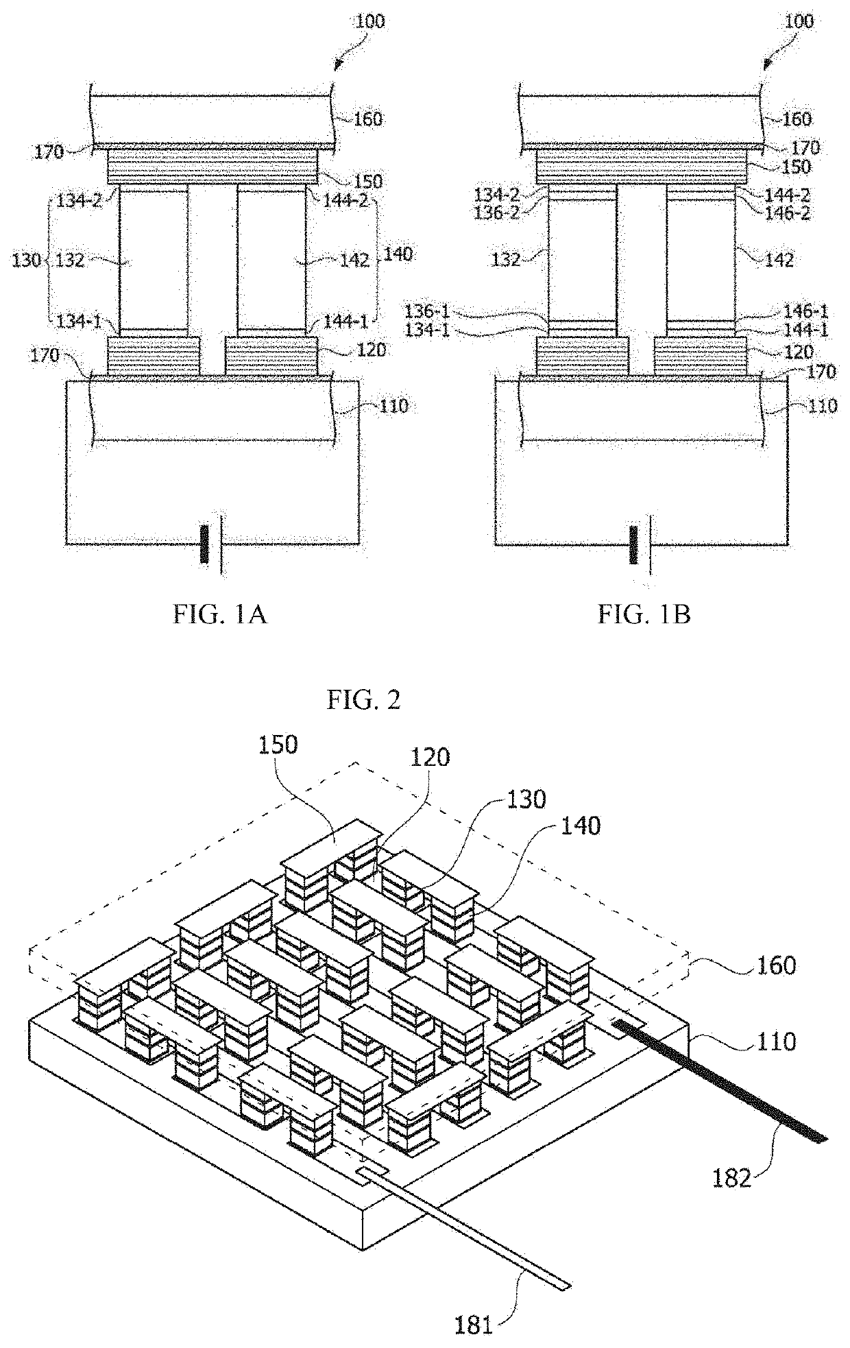
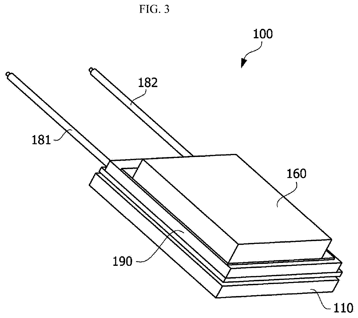
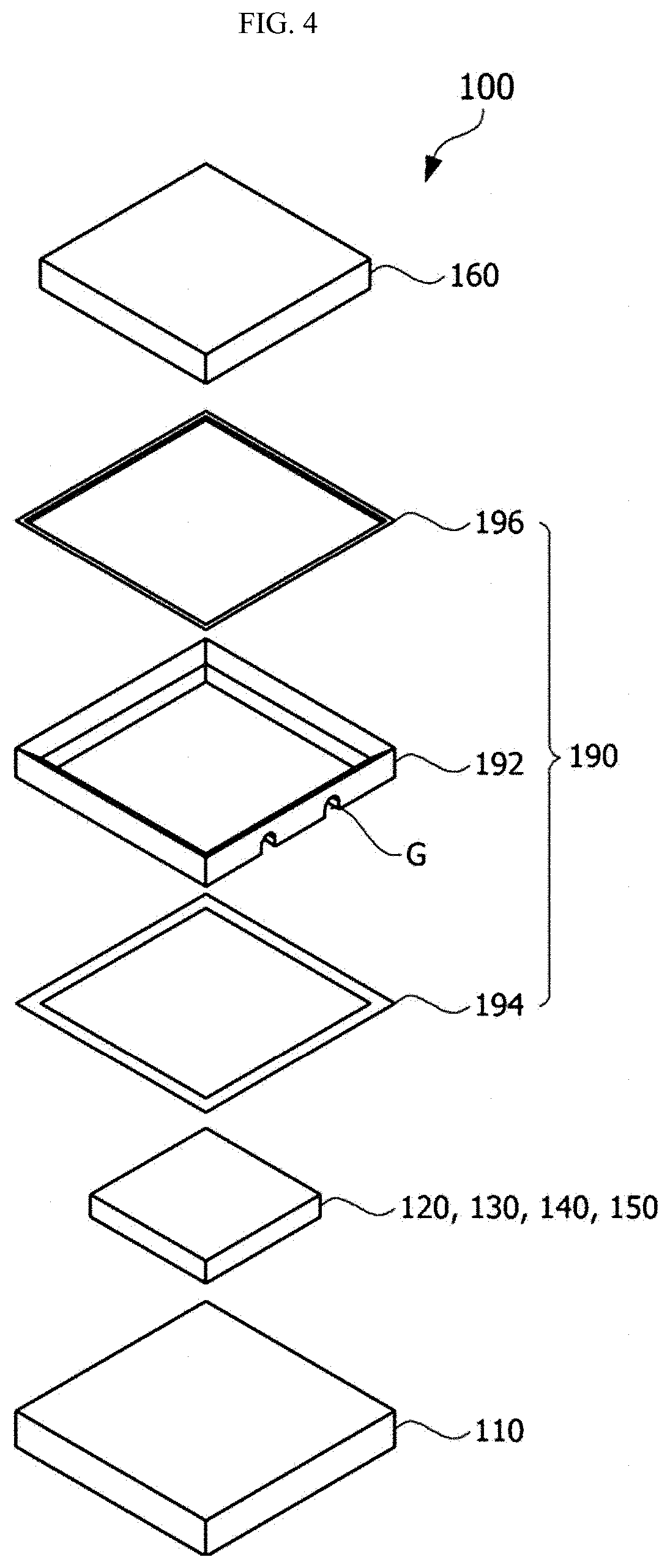
[0036]Hereinafter, exemplary embodiments of the present invention will be described in detail with reference to the accompanying drawings.

[0037]However, the technical spirit of the present invention is not limited to some embodiments which will be described and may be realized using various other embodiments, and at least one component of the embodiments may be selectively coupled, substituted, and used within the range of the technical spirit.

[0038]In addition, unless clearly and specifically defined otherwise by context, all terms (including technical and scientific terms) used herein can be interpreted as having customary meanings to those skilled in the art, and meanings of generally used terms, such as those defined in commonly used dictionaries, will be interpreted by considering contextual meanings of the related technology.

[0039]In addition, the terms used in the embodiments of the present invention are considered in a descriptive sense and not for...


PUM

PropertyMeasurementUnit
thicknessaaaaaaaaaa
thicknessaaaaaaaaaa
thicknessaaaaaaaaaa

Abstract

A thermoelectric device according to one embodiment of the present invention includes a first insulating layer, a first substrate disposed on the first insulating layer, a second insulating layer disposed on the first substrate, a first electrode disposed on the second insulating layer, a P-type thermoelectric leg and an N-type thermoelectric leg disposed on the first electrode, a second electrode disposed on the P-type thermoelectric leg and the N-type thermoelectric leg, a third insulating layer disposed on the second electrode, and a second substrate disposed on the third insulating layer, wherein the first insulating layer includes a first aluminum oxide layer, the first substrate is an aluminum substrate, the second substrate is a copper substrate, the first substrate is a low temperature portion, and the second substrate is a high temperature portion.

Description

CROSS-REFERENCE TO RELATED APPLICATIONS[0001]This application is the U.S. national stage application of International Patent Application No. PCT / KR2020 / 006946, filed May 28, 2020, which claims the benefit under 35 U.S.C. § 119 of Korean Application No. 10-2019-0066648, filed Jun. 5, 2019, the disclosures of each of which are incorporated herein by reference in their entirety.TECHNICAL FIELD[0002]The present invention relates to a thermoelectric device, and more specifically, to a substrate and an insulating layer of a thermoelectric device.BACKGROUND ART[0003]A thermoelectric effect is a phenomenon occurring due to movement of electrons and holes in a material, and the thermoelectric effect means direct energy conversion between heat and electricity.[0004]A thermoelectric device is a generic term for devices using a thermoelectric effect and has a structure in which P-type thermoelectric legs and N-type thermoelectric legs are bonded between metal electrodes to form PN junction pair...

Claims


Application Information

Patent Timeline
Patent Type & Authority Applications(United States)
IPC IPC(8): H01L35/20H01L35/32
CPCH01L35/20H01L35/32H10N10/80H10N10/00H10N10/13H10N10/17H10N10/854
Inventor CHOI, MAN HUECHO, YONG SANG
Owner LG INNOTEK CO LTD
Why Eureka
Try Eureka