Dressing Tool and Method for the Production Thereof

Pending Publication Date: 2022-10-06
REISHAUER
View PDF0 Cites 0 Cited by
  • Summary
  • Abstract
  • Description
  • Claims
  • Application Information

AI Technical Summary

Benefits of technology

The invention is a dressing tool for profiling grinding worms that solves the problem of slow and inaccurate profiling. The tool has multiple profiles arranged coaxially and a metallic main body with the profiles formed by a negative process using a casting compound. This design increases the service life of the tool and reduces the cost of manufacturing. The tool has conical or cylindrical profiles, which make it highly effective in profiling grinding worms. Additionally, the tool has a negative mold and complementary profile forms, which fixes special hard-material particles to protect the tool from wear during the profiling process. Overall, this invention provides a compact, precise, and cost-effective tool for profiling grinding worms.

Problems solved by technology

In this situation, the correct adjustment to the geometry of the work gear flank is essential, and leads to very limited flexibility in application.
With these tools, however, comparatively short dressing times can be achieved.
This dressing tool is relatively elaborate and expensive to produce, but despite that it is still unsuitable for high-precision profiling.
This also means that it is also not possible to produce high-precision flank profiles on the grinding worm, which has a directly negative effect on the precision of the gear wheels which are to be produced.
The main problem with many of these different dressing techniques is the fact that, in spatial terms, there are always two spatial working surfaces moving on the worm flank and on the dressing tool, and in this context these surfaces are often also composed of part surfaces.
When this occurs, even with the most careful arrangement of the dressing profile, it is very often the case that the resulting quality of dressing and grinding is inadequate.
Due to the contact of a full-profile roller over multiple grinding worm threads, however, a correction of a profile angle deviation is not possible.

Method used


Image

  • Dressing Tool and Method for the Production Thereof
  • Dressing Tool and Method for the Production Thereof
  • Dressing Tool and Method for the Production Thereof

Examples


Embodiment Construction

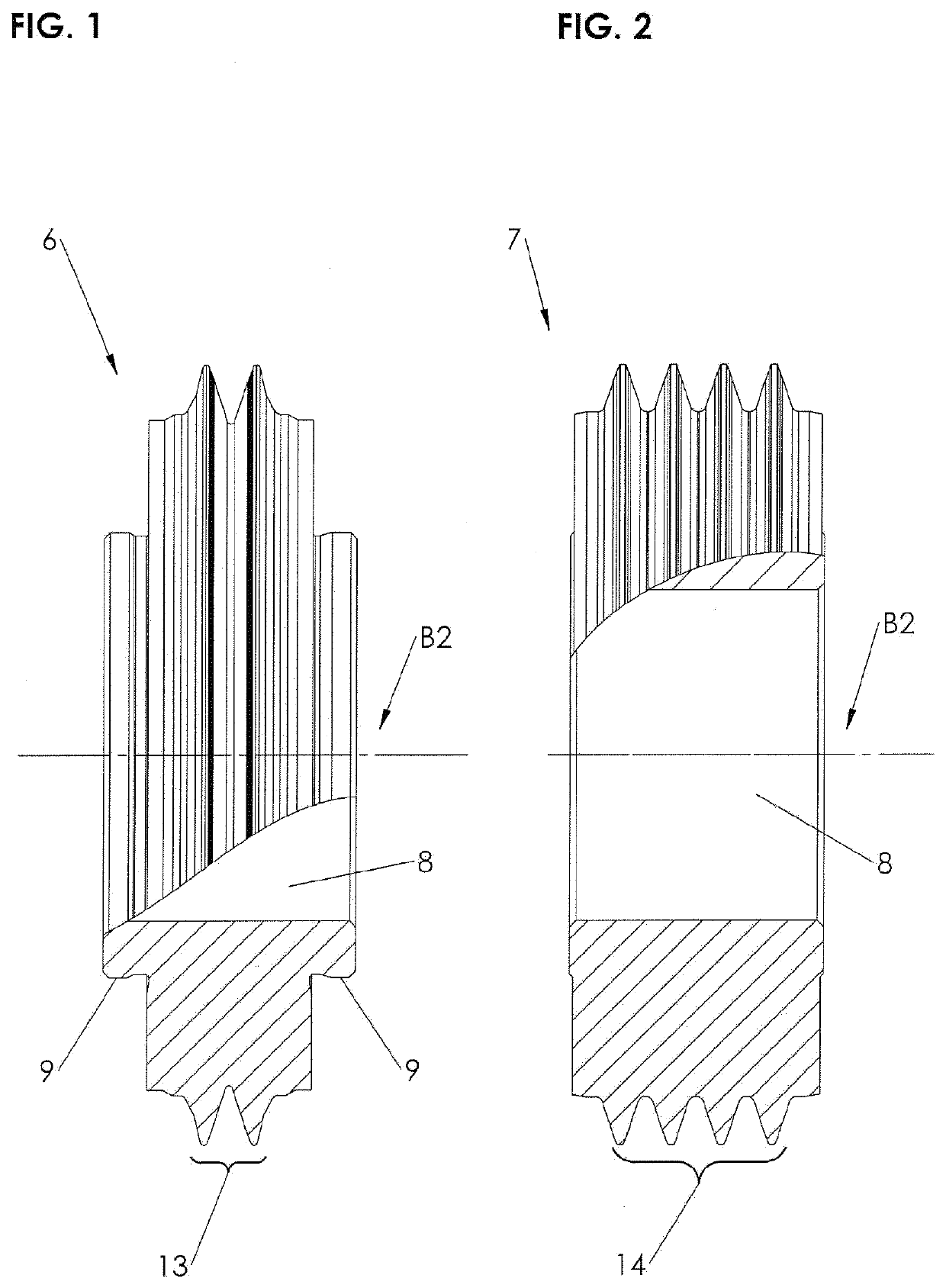
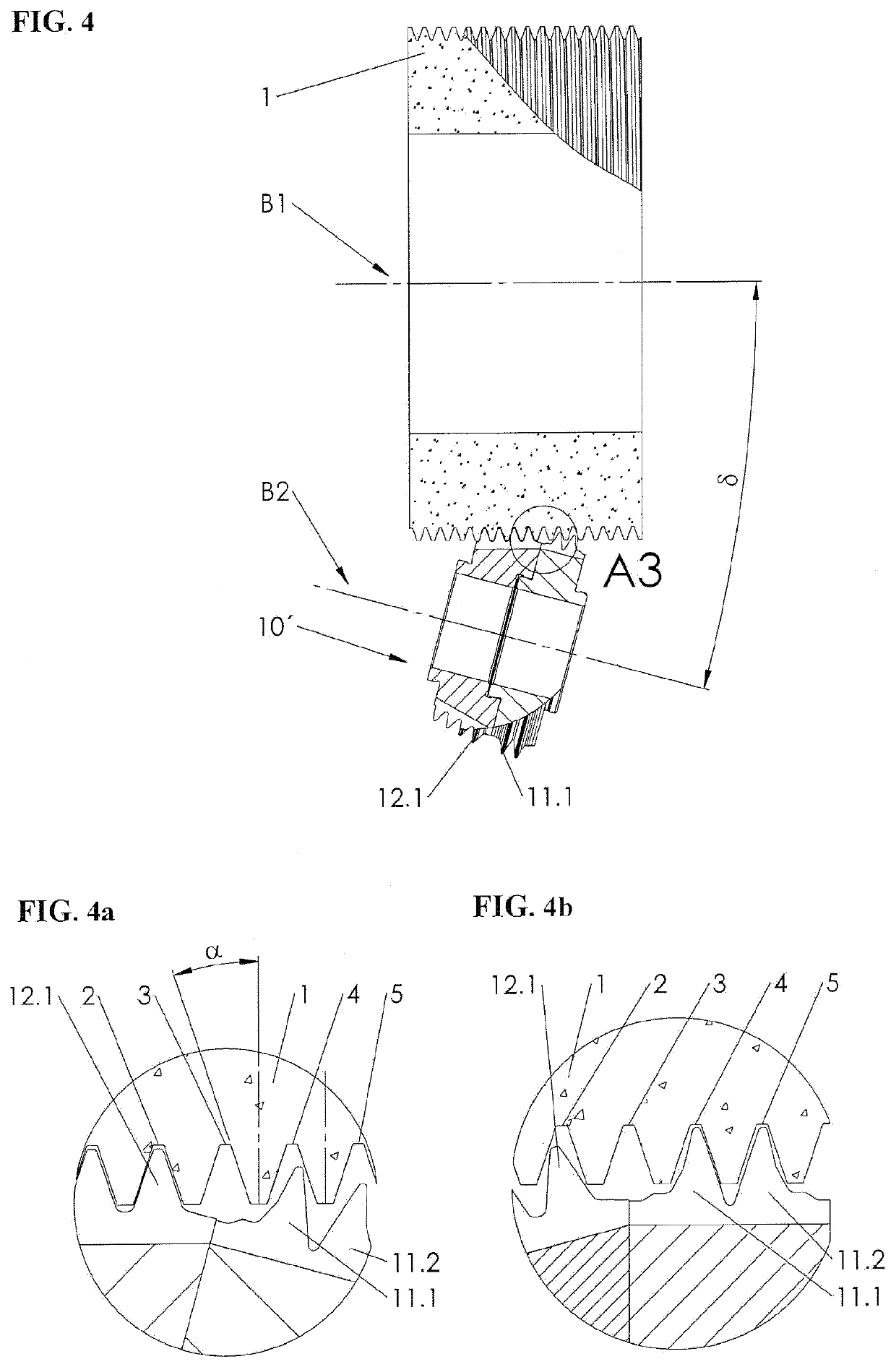
[0028]FIG. 1 and FIG. 2 each show a known dressing tool 6, 7, which serves to carry out the profiling of the flanks of grinding worms 1 which can be dressed, and which in turn are used for the grinding of correspondingly configured gear wheels. Advantageously, such dressing tools 6, 7 are suitable for gear wheels in the module range from 0.15 to 5 mm. Represented in each case are the rotation axles B2, the holes 8, and the testing collars 9 arranged on both sides in the form of a hub.

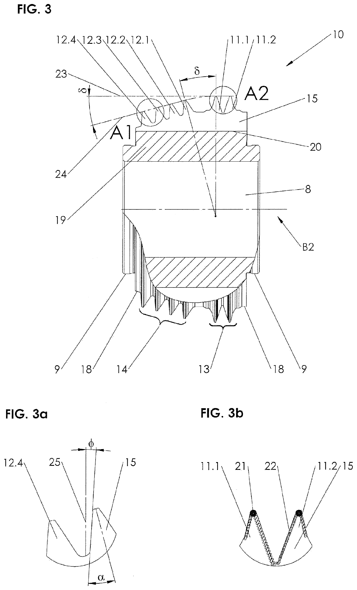
[0029]With the dressing tools 6 and 7, which are configured as what are referred to as set-profile rollers and full-profile rollers, the profiles 11.1, 11.2, and respectively 12.1, 12.2, 12.3, 12.4, are formed by profile grooves, of which the working surfaces 13 and 14 respectively are formed by opposing flanks with head regions and feet regions, and which are provided with corresponding hard-material particles 21, 22.

[0030]FIG. 3 shows a dressing tool 10, which is provided with profiles 11.1, 11.2, 12....


PUM


Abstract

Dressing tool which has profiled elements arranged coaxially with one another and which are each provided with a profile form, which is tapered or the like in its axial cross-section and has working surfaces provided with hard-material particles. The profiled elements are delimited at their outer circumference by at least one generated surface. The dressing tool preferably includes six profiled elements arranged coaxially with one another, and a one-part or two-part metallic main body for the entire dressing tool or for a particular generated surface. The profile forms with the hard-material particles of the profiled elements may be produced by a negative process with a casting compound applied to the particular main body. This dressing tool can thus be used for a profiling of grinding worms extremely productively and precisely and also such that they can be corrected.

Description

FIELD OF THE INVENTION[0001]The invention relates to a dressing tool with profiles arranged coaxially to one another, each with a profile form in conical or similar shape in axial cross-section and with working surfaces provided with hard-material particles, wherein the profiles are delimited at the outer circumference by at least one surface, and a method for its production.BACKGROUND OF THE INVENTION[0002]The dressing of grinding worms is itself a very demanding generating machining process in the field of roll grinding, which is based on a large number of synchronized and highly precise individual movements and is carried out by special dressing tools. For high productivity rates, full-profile rolls are used as typical rotating dressing tools for the lower module region, which are characterized by the fact that they combine all the profiling tasks for the worm flanks, heads, and feet in one tool. In this situation, the correct adjustment to the geometry of the work gear flank is ...

Claims


Application Information

Patent Timeline
IPC IPC(8): B24B53/12B24B53/075B24D18/00
CPCB24B53/12B24B53/075B24D18/00B24D18/0018B24B53/053B24B53/07B24D18/0009
Inventor PAVLOVIC, MARINMONTEIRO FERREIRA, SERGIO MANUELRUDOLF, CHRISTOPH
Owner REISHAUER
Why Eureka
Try Eureka