
Stator tooth with stator-tooth arc-cutting structure

a stator tooth and arc-cutting technology, which is applied in the direction of dynamo-electric machines, electrical equipment, magnetic circuit shapes/forms/construction, etc., can solve the problems of magnet demagnetization, total harmonic distortion of counter electromotive force and torque ripples, etc., and achieve the effect of reducing the effect of cogging torque and torque ripples

Inactive Publication Date: 2022-09-29
TECO ELECTRIC AND MACHINERY
View PDF12 Cites 0 Cited by
  • Summary
  • Abstract
  • Description
  • Claims
  • Application Information

AI Technical Summary

Benefits of technology

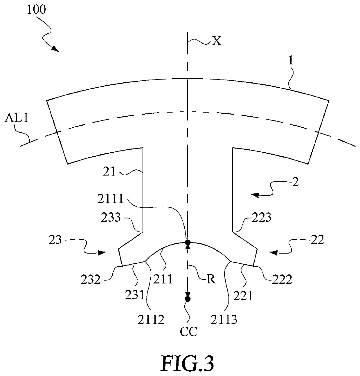
The present invention aims to provide a stator tooth with a structure that can reduce the effects of cogging torque and torque ripples without arc-cutting the magnet. The stator tooth is designed with a unique arc-cutting structure that includes a first inner arc-shaped edge and two second inner arc-shaped edges. By creating the first inner arc-shaped edge in the middle of the two second inner arc-shaped edges, the concave arc-cutting structure can be formed. This design helps to maintain a high level of magnetic flux between the rotor and stator, while reducing rotational resistance and inhibiting cogging torque and torque ripples.

Problems solved by technology

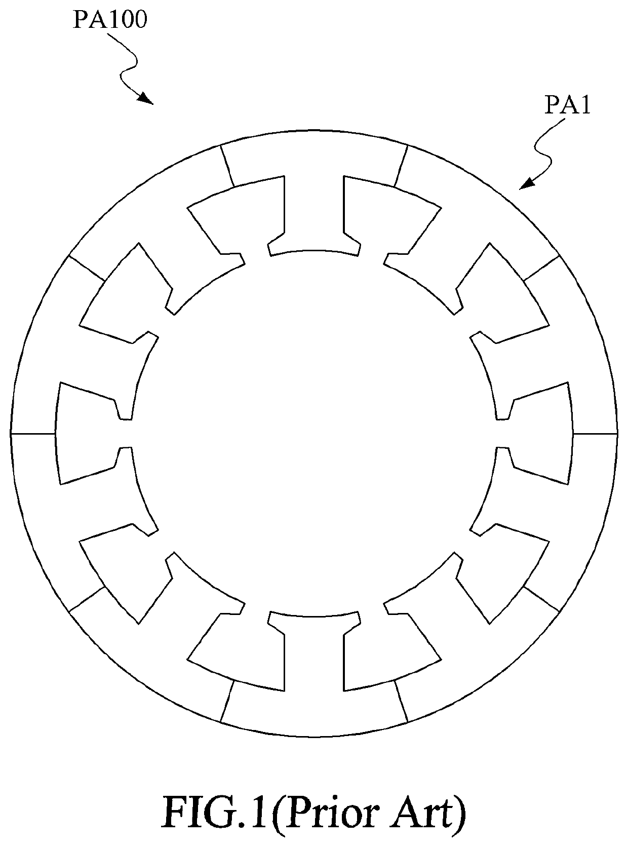
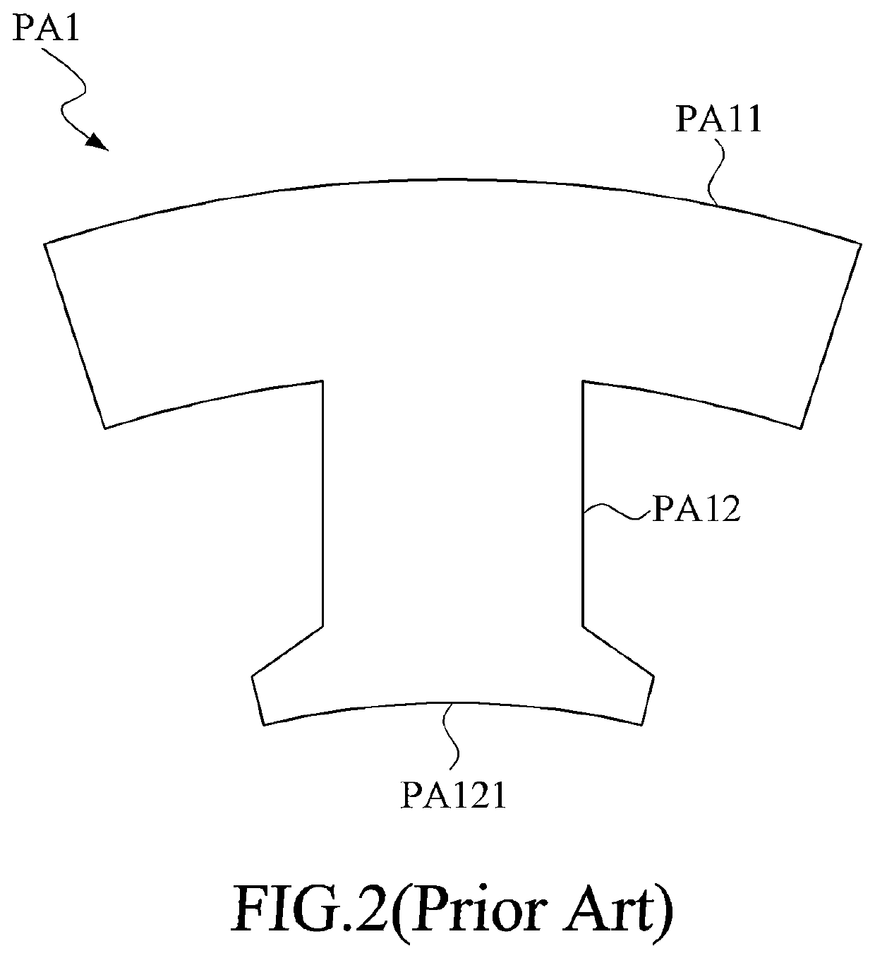
However, when the pole of the coil at the stator tooth PA1 is different to that of the magnet at the rotor, a repulsive force against rotation of the rotor would be formed, and from which abnormal phenomena such as cogging torque at the rotor, total harmonic distortion of the counter electromotive force and torque ripples would be formed.
Even more seriously, the consequence may cause the magnet to demagnetization, and by which normal operation of the motor might be retarded.

Method used


Image

  • Stator tooth with stator-tooth arc-cutting structure
  • Stator tooth with stator-tooth arc-cutting structure
  • Stator tooth with stator-tooth arc-cutting structure

Examples


Embodiment Construction

[0026]The invention disclosed herein is directed to a stator tooth with a stator-tooth arc-cutting structure. In the following description, numerous details are set forth in order to provide a thorough understanding of the present invention. It will be appreciated by one skilled in the art that variations of these specific details are possible while still achieving the results of the present invention. In other instance, well-known components are not described in detail in order not to unnecessarily obscure the present invention.

[0027]Referring to FIG. 3, an embodiment of the stator tooth with a stator-tooth arc-cutting structure in accordance with the present invention is schematically shown. In this embodiment, the stator tooth with a stator-tooth arc-cutting structure 100 includes an arc-shaped stator yoke portion 1 and a stator tooth portion 2.

[0028]The arc-shaped stator yoke portion 1 is extended along an arc AL1. The stator tooth portion 2 includes a tooth body segment 21 and ...


PUM


Abstract

A stator tooth includes an arc-shaped stator yoke portion and a stator tooth portion. The arc-shaped stator yoke portion extends along an arc having an axis as a center. The stator tooth portion includes a tooth body segment and two shoe-shaped structures. The tooth body segment, protruding along a centripetal axis from the arc-shaped stator yoke portion, has a first inner arc-shaped edge defined with a first center and a first radius. The centripetal axis passes through a center point of first inner arc-shaped edge, the first center and the axis. The two shoe-shaped structures extend oppositely, but symmetrically, from the tooth body segment, and each the shoe-shaped structure has a second inner arc-shaped edge and an inner-edge end point. The second inner arc-shaped edge, extending from the first inner arc-shaped edge to the inner-edge end point, has a second radius larger than the first radius.

Description

[0001]This application claims the benefit of Taiwan Patent Application Serial No. 110111062, filed Mar. 26, 2021, the subject matter of which is incorporated herein by reference.BACKGROUND OF THE INVENTION(1) Field of the Invention[0002]The invention relates to a stator tooth, and more particularly to a stator tooth with a stator-tooth arc-cutting structure.(2) Description of the Prior Art[0003]Generally speaking, according to structural differences, motors can be roughly divided into synchronous motors, induction motors, reversible motors, stepping motors, servo motors and linear motors. Among all, with various advantages in constant speed, low starting torque, stable speed and high efficiency, the synchronous motors are widely applied to versatile fields such as automatic production equipment, refrigeration and air conditioning, and power equipment.[0004]As described above, the synchronous motor mainly provides an alternating current to the coil of the stator, and then generates a...

Claims


Application Information

Patent Timeline
IPC IPC(8): H02K1/14
CPCH02K1/146H02K2213/03H02K1/148H02K29/03
Inventor HUNG, LIAN-SHINHUANG, CHING-CHIHLI, YU-DE
Owner TECO ELECTRIC AND MACHINERY
Learn More