
Nacelle air intake provided with a mixed ice protection system

a technology of mixed ice protection system and nacelle, which is applied in the direction of mechanical equipment, machines/engines, transportation and packaging, etc., can solve the problems of worse performance levels

Active Publication Date: 2022-09-08
AIRBUS OPERATIONS (SAS)
View PDF3 Cites 1 Cited by
  • Summary
  • Abstract
  • Description
  • Claims
  • Application Information

AI Technical Summary

Benefits of technology

The present invention proposes a nacelle air intake that improves ice protection and allows for better acoustic performance. The design also allows for defrosting of the outer face of the air intake. Additionally, a reheating panel is included to provide hot air to the air intake without interfering with the acoustic panel. These improvements enhance the overall performance and efficiency of the nacelle.

Problems solved by technology

Because of the placement of the ice elimination system at least on the outer face, the blocks of ice are driven by the air stream licking the outer face and are in practice not ingested by the engine which could worsen the performance levels thereof.

Method used


Image

  • Nacelle air intake provided with a mixed ice protection system
  • Nacelle air intake provided with a mixed ice protection system
  • Nacelle air intake provided with a mixed ice protection system

Examples


Embodiment Construction

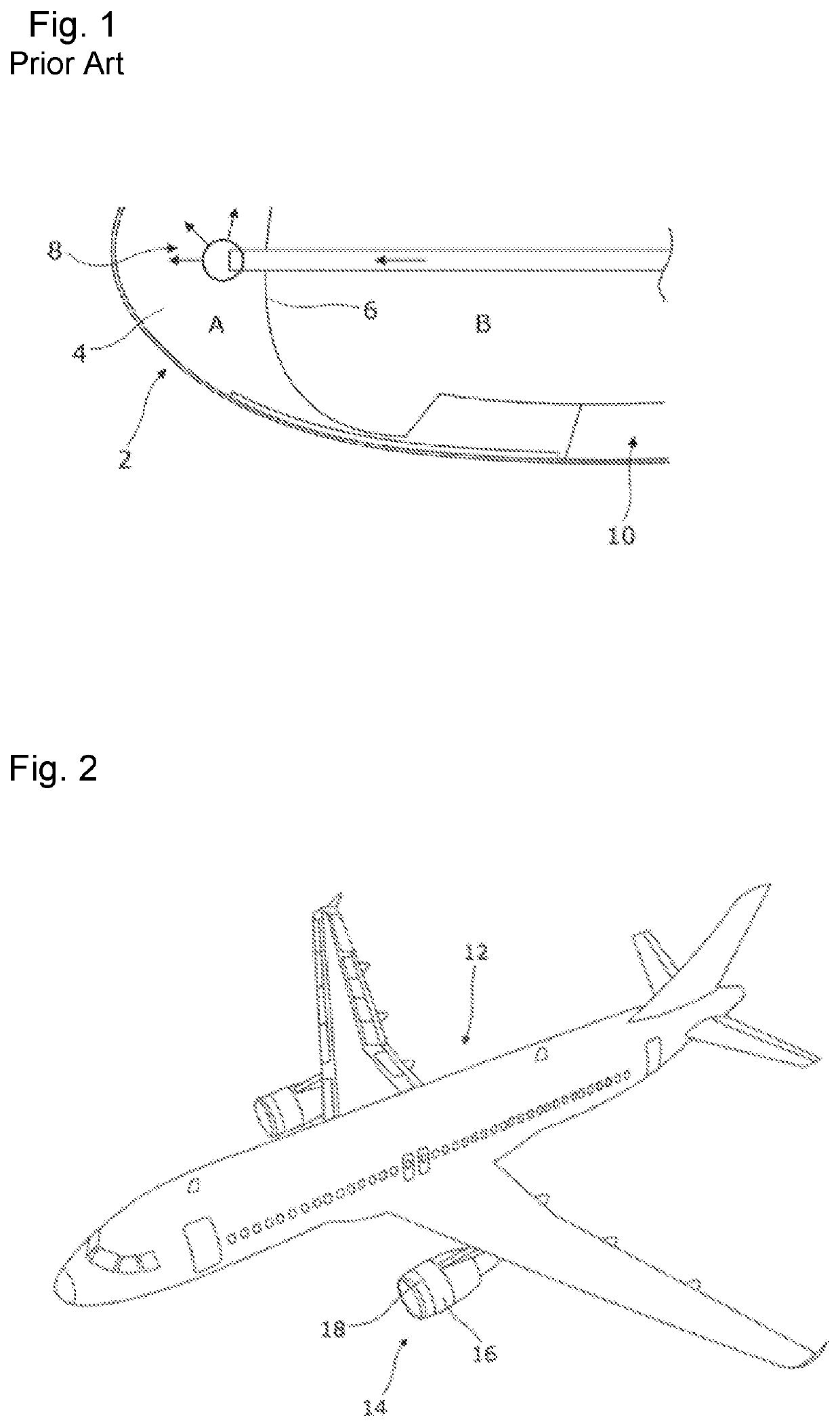
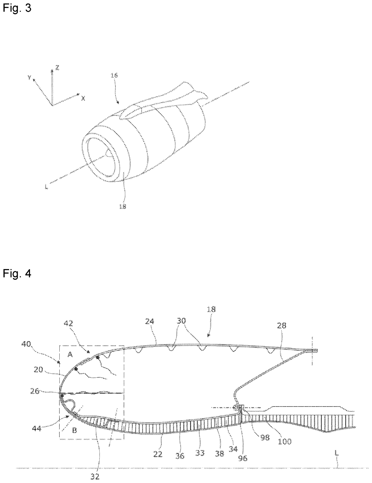
[0044]FIG. 2 represents an aircraft 12 comprising a propulsive assembly 14. The propulsive assembly 14 is a device making it possible to generate a thrust which constitutes the propelling force of the aircraft 12. The propulsive assembly 14 comprises a nacelle 16 surrounding an engine such as a jet engine having an air intake 18. As illustrated in FIG. 3, the nacelle 16 extends around an axis called longitudinal axis L oriented in a longitudinal direction X. The direction Y corresponds to the direction oriented transversely with respect to the nacelle 16. The direction Z corresponds to the vertical or height wise direction when the aircraft is resting on the ground. The three directions X, Y and Z are mutually orthogonal. Hereinafter in the description, the terms “front” and “rear”, “upstream” and “downstream” are understood according to the direction of the air stream in the propulsive assembly in operation, i.e., the direction X. The air enters through the front of the propulsive ...


PUM


Abstract

An optimized protection against ice on the inner and outer faces of an aircraft engine nacelle air intake with the air intake including an outer face and an inner face meeting at a line at the longitudinally extreme, called extremum line, an acoustic panel being installed on the inner surface of a part of the inner face. An elimination system based on vibration of the ice formed is put in place on at least a part of the outer face and an ice formation prevention system using a hot fluid is put in place on at least a part of the inner face and either an ice elimination system or an ice formation prevention system using a hot fluid is installed on the inner face and on the outer face, a marking line marking the boundary between the two systems.

Description

CROSS-REFERENCES TO RELATED APPLICATIONS[0001]This application claims the benefit of the French patent application No. 2102075 filed on Mar. 3, 2020, the entire disclosures of which are incorporated herein by way of reference.FIELD OF THE INVENTION[0002]The present invention relates to aircraft propulsive assemblies and more particularly the air intake of the nacelles of the propulsive assemblies.BACKGROUND OF THE INVENTION[0003]Conventionally, an aircraft nacelle comprises, from front to rear, a first section upstream in the direction of the aerodynamic flow passing through the nacelle of the aircraft in flight, called air intake, a second section which covers the casing of the engine fan, called fan cowl, and a third section which generally has a thrust reversing zone which surrounds the body of the turbine of the engine downstream in the direction of the aerodynamic flow.[0004]The leading edges of the aircraft, and, in particular, the lips of the air intakes of the nacelles of th...

Claims


Application Information

Patent Timeline
IPC IPC(8): F02C7/047F02C7/24
CPCF02C7/047F02C7/24F05D2260/96B64D33/02B64D2033/0233B64D2033/0206B64D15/02B64D15/163F02C7/045F02C6/06
Inventor BOURHIS, ARNAUDALBET, GREGORYPORTE, ALAIN
Owner AIRBUS OPERATIONS (SAS)
Learn More