Transparent heating film
a technology of transparent film and conductive film, which is applied in the direction of electric heating, ohmic resistance heating, melt circulation arrangements, etc., can solve the problem that users may not be able to recognize the attached conductive film, and achieve excellent electrical conductivity, excellent transparency, and easy installation
- Summary
- Abstract
- Description
- Claims
- Application Information
AI Technical Summary
Benefits of technology
Problems solved by technology
Method used
Image

Examples
first embodiment
1. First Embodiment
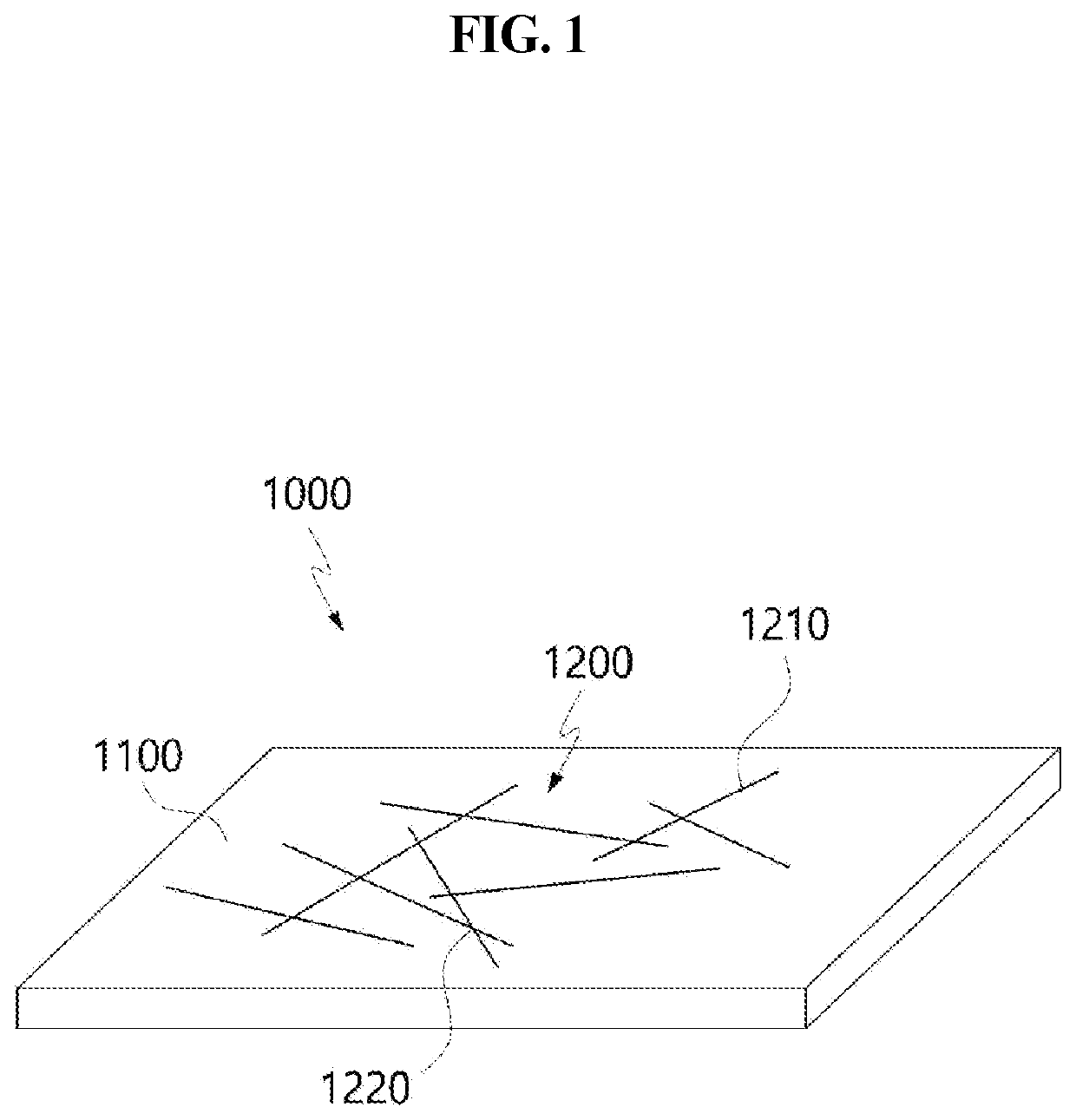
[0053]FIG. 1 is a perspective view of a transparent heating film according to a first embodiment.
[0054]Referring to FIG. 1, a transparent heating film 1000 includes a transparent substrate 1100 and a conductive network 1200. The conductive network 1200 includes intersection points 1220 formed since different metal nanostructures 1210 intersect with each other.
[0055]The transparent heating film 1000 may be attached to a transparent target member. The target member may be a base material on which the transparent conductive film 1000 is installed. The target member may be a member for maintaining the shape of the transparent conductive film 1000. The transparent conductive film 1000 may be installed on one surface of the target member. The other surface of the target member opposite to the one surface may be in contact with the outside air. The temperatures of one surface and the other surface of the target member may be different from each other.
[0056]The target mem...
second embodiment
2. Second Embodiment
[0126]Hereinafter, a transparent heating film according to a second embodiment will be described.
[0127]The transparent heating film according to the second embodiment is the same as the first embodiment except that a bus bar 1300 and a coating layer 1400 are further included in the transparent heating film according to the first embodiment. Accordingly, in the description of the second embodiment, the same reference numerals are assigned to the components common to the first embodiment, and detailed descriptions thereof are omitted.
[0128]FIG. 6 is a perspective view of a transparent heating film according to a second embodiment.
[0129]Referring to FIG. 6, the transparent heating film 1000 includes a transparent substrate 1100, a conductive network 1200, a bus bar 1300, and a coating layer 1400.
[0130]The bus bar 1300 may be located on the top surface 1110 of the transparent substrate 1100. The bus bar 1300 may be located on at least a partial area of the conductive...
third embodiment
3. Third Embodiment
[0171]Hereinafter, a transparent heating film according to a third embodiment will be described. The transparent heating film according to the third embodiment is the same as the above-described embodiments except for those described below. Accordingly, in the description of the third embodiment, the same reference numerals are assigned to the components common to the above-described embodiments, and detailed descriptions thereof are omitted.
[0172]FIG. 9 is a perspective view of the transparent heating film according to the third embodiment. Referring to FIG. 9, the transparent heating film 1000 includes a transparent substrate 1100, a conductive network 1200, and an adhesive layer 1500. The transparent substrate 1100 includes a top surface 1110 and a bottom surface 1120. The conductive network 1200 includes intersection points 1220 formed by different metal nanostructures 1210 which intersect with each other.
[0173]The transparent substrate 1100 may be used for fi...
PUM
 Abstract
Description
Claims
Application Information
 - R&D
- Intellectual Property
- Life Sciences
- Materials
- Tech Scout
- Unparalleled Data Quality
- Higher Quality Content
- 60% Fewer Hallucinations
Browse by: Latest US Patents, China's latest patents, Technical Efficacy Thesaurus, Application Domain, Technology Topic, Popular Technical Reports.
© 2025 PatSnap. All rights reserved.Legal|Privacy policy|Modern Slavery Act Transparency Statement|Sitemap|About US| Contact US: help@patsnap.com