
Rotary air preheater

a rotary air preheater and air preheater technology, which is applied in indirect carbon dioxide mitigation, combustion treatment, lighting and heating apparatus, etc., can solve the problems of reducing the temperature of purging steam to about 100 to 150°, the effect of the conventional steam sootblower, and the limitation of the sootblower

Active Publication Date: 2022-08-25
SUZHOU XIRE ENERGY SAVING ENVIRONMENTAL PROTECTION TECH CO LTD
View PDF11 Cites 1 Cited by
  • Summary
  • Abstract
  • Description
  • Claims
  • Application Information

AI Technical Summary

Benefits of technology

The present patent describes improvements to a nozzle assembly for removing ash deposition from ammonium bisulfate. The nozzle assemblies improve the purging effect by heating and gasifying the ash deposition, making it easier to remove. The design also ensures uniform steam purging by increasing the amount of heated and purged steam in different radial zones of the rotor. This avoids overblowing heat exchange elements at the inner side and underblowing them at the outer side. Overall, the technical solutions improve the efficiency of ash deposition removal.

Problems solved by technology

In the above technologies of the steam sootblower of air preheater, CN204881327 increases the residence time of the heat exchange element of the air preheater rotor on steam blowing section in the circumference, however, for highly cohesive ash deposition containing ammonium bisulfate, the effect of the conventional steam sootblower is limited, the main reason is that when the jet steam reaches the surface of the heat exchange element, although the central jet velocity is still retained at 80 to 120 m / s, the purging steam temperature decreases to about 100 to 150° C. due to the entrainment of the surrounding low-temperature flue gas.
For the highly cohesive ash deposition containing ammonium bisulfate, even though the steam jet has strong scouring and shearing effects, due to the low temperature of the jet steam, the intensity of ash deposition cannot be weakened by heating and gasifying the ammonium bisulfate in the ash deposition, which also seriously reduces the purging effect of the steam sootblower on ash deposition of ammonium bisulfate.

Method used


Image

  • Rotary air preheater
  • Rotary air preheater
  • Rotary air preheater

Examples


Embodiment Construction

[0023]In the following, the technical schemes of the present disclosure are explained clearly and completely below in conjunction with the drawings, and apparently, the described embodiments are merely a few of the embodiments of the present disclosure, not all the embodiments.

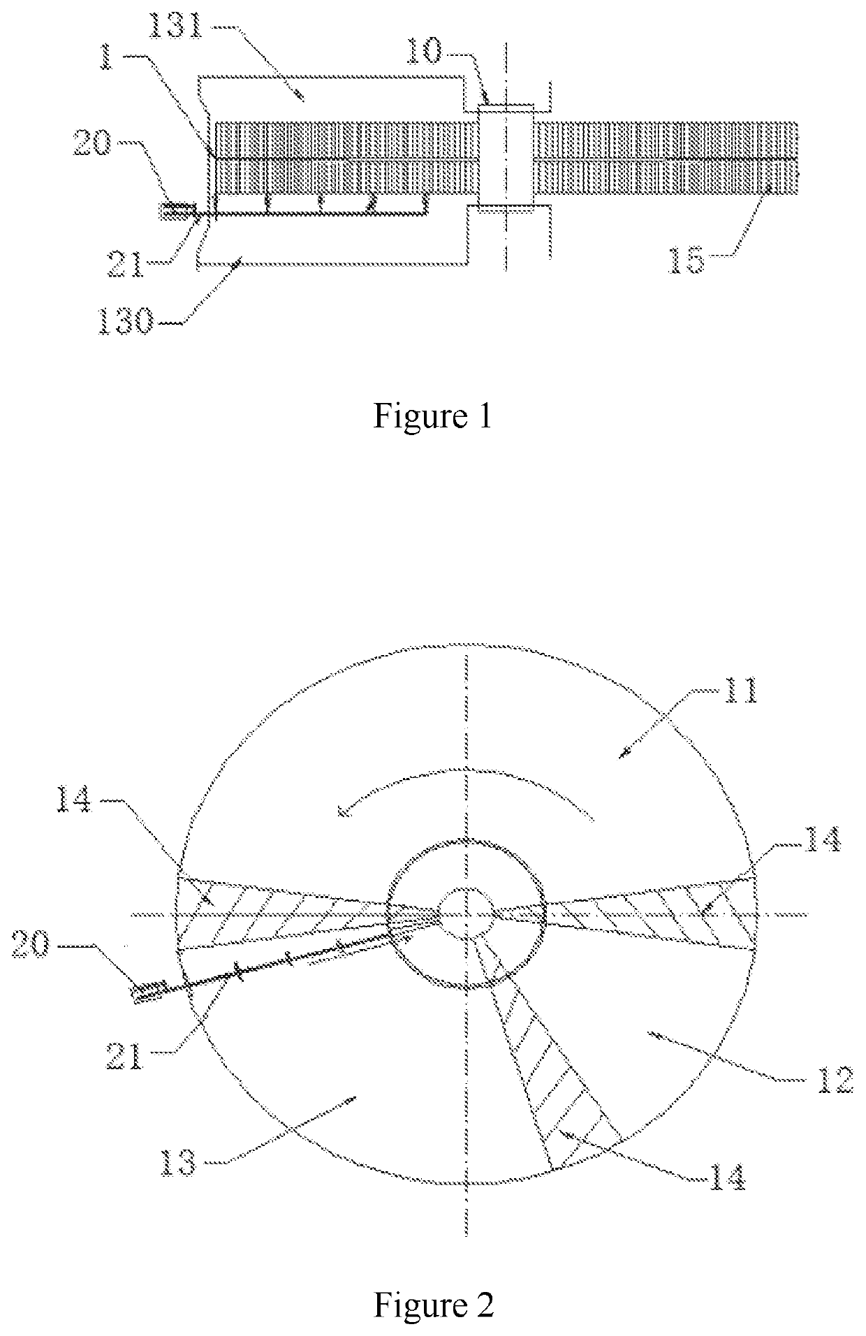
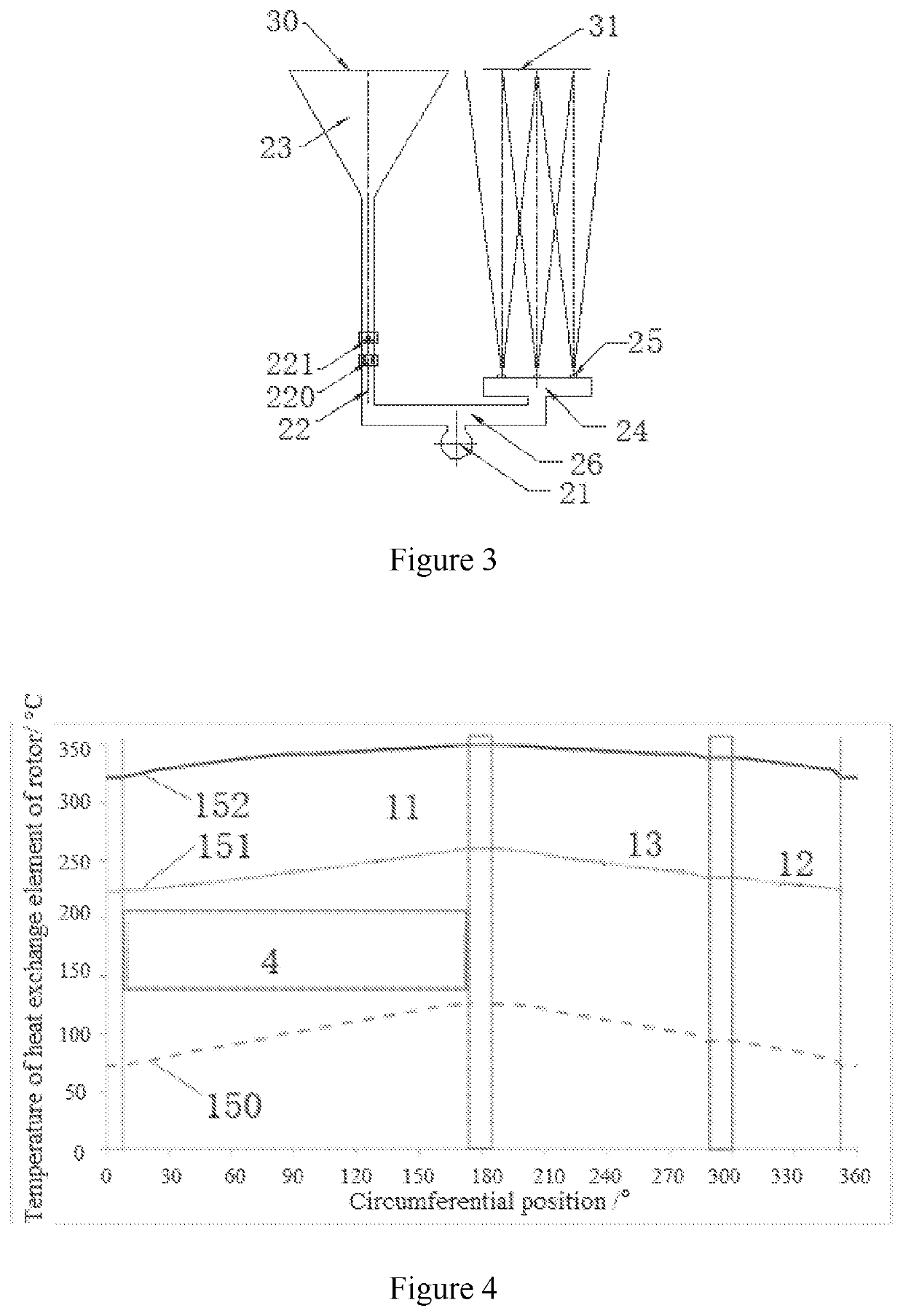
[0024]A rotary air preheater with a steam soot-blowing device, as shown in FIG. 1 and FIG. 2, comprises a rotor 1 rotating around a central sleeve 10, wherein a flue gas section 11, a primary air section 12 and a secondary air section 13 are arranged within the rotor 1 in its circumferential direction, the flue gas section 11, the primary air section 12 and the secondary air section 13 are separated by a seal 14, and a metallic heat exchange element 15 is arranged on the rotor 1. The rotation process passes through the flue gas section 11, the secondary air section 13 and the primary air section 12 in sequence to carry out periodic heat storage and heat release processes as following: in the flue gas section 1...


PUM


Abstract

A rotary air preheater is provided, including: a rotor and a steam soot-blowing device arranged in a cold secondary air inlet channel of secondary air section. The steam soot-blowing device includes a steam sootblower, a first pipe communicating with the steam sootblower and extending in a radial direction of the rotor, and nozzle assemblies communicating with the first pipe. The nozzle assembly includes a first nozzle assembly and a second nozzle assembly, and the first nozzle assembly is located upstream of the second nozzle assembly in a rotational direction of the rotor. The first nozzle assembly includes a sprayer, and diameter of an inlet of the sprayer is smaller than diameter of an outlet thereof. The second nozzle assembly includes at least one nozzle, and steam jet velocity at the outlet of the sprayer is greatly smaller than steam jet velocity at an outlet of the nozzle.

Description

CROSS-REFERENCE TO RELATED APPLICATION[0001]This application is a continuation application to PCT / CN2020 / 140605, having a filing date of Dec. 29, 2020, the entire contents of which are incorporated herein by reference.FIELD OF TECHNOLOGY[0002]The following relates to a rotary air preheater.BACKGROUND[0003]Coal-fired utility boiler is conventionally equipped with a rotary air preheater, which includes a flue gas section, a secondary air section and a primary air section in a circumferential direction, wherein a rotor consisted of upper and lower layers of flat-plate heat exchange elements passes through the flue gas section, the secondary air section and the primary air section in sequence during it rotates, to carry out periodic heat storage and heat release processes as following: in the flue gas section, the high-temperature flue gas flows through the heat exchange elements from top to bottom, the flue gas releases heat and its temperature decreases, and the heat exchange elements...

Claims


Application Information

Patent Timeline
Patent Type & Authority Applications(United States)
IPC IPC(8): F23L15/04F23J3/02
CPCF23L15/04F23J3/02F23L2900/15041F23J2700/001F28G1/16F23L15/02Y02E20/34
Inventor SONG, YUBAOXIE, XINHUAZHAO, XUECHENGHE, JINLIANGWEI, ZHENZU
Owner SUZHOU XIRE ENERGY SAVING ENVIRONMENTAL PROTECTION TECH CO LTD
Learn More