Nozzle plate nozzle plate manufacturing method and inkjet head

a technology of nozzle plate and manufacturing method, which is applied in the direction of printing, inking apparatus, etc., can solve the problems of inability to eject ink, small decrease in ejection amount or no nozzle ejection (also referred to as nozzle missing), and satellites, etc., to achieve excellent abrasion resistance, improve the adhesion of metal substrates, and improve the effect of alkali ink resistan

Pending Publication Date: 2022-08-25
KONICA MINOLTA INC
View PDF0 Cites 0 Cited by
  • Summary
  • Abstract
  • Description
  • Claims
  • Application Information

AI Technical Summary

Benefits of technology

[0034]According to the present invention, it is possible to provide a nozzle plate exhibiting excellent abrasion resistance, alkali ink resistance, liquid repellency on the surface of the nozzle plate when ink is jetted and the like.
[0035]The expression mechanism or action mechanism of the effect of the present invention is inferred as follows.
[0036]In the present invention, the base layer, the intermediate layer, and the liquid repellent layer that constitute the nozzle plate are constituted as specified in the present invention, so that the silane coupling agents having reactive functional groups on both terminals and including a hydrocarbon chain and a benzene ring at an intermediate part added to the base layer polymerize densely and produce stacking interactions with each other, whereby the adhesion a the metal substrate is particularly improved, and when the nozzle plate is subjected to stress, particularly in the thickness direction, the adhesion between the substrate of the nozzle plate and the constituent layers provided thereon can be improved, and the resistance when the surface of the nozzle plate is subjected to stress in the width direction by a wiping material or the like used during maintenance can be improved. Further, it has been found that by providing the intermediate layer, the coupling agent in the liquid repellent layer can be efficiently oriented on the surface and can be densely filled on the flat surface, and it is possible to realize excellent liquid repellency, as well as alkali durability and to ensure durability against long-term repeated maintenance using pigment ink.

Problems solved by technology

When ink droplets or dust adhere to the vicinity of the nozzle hole of the inkjet head, the ejection direction of the ink droplets to be ejected is bent, or the ejection angle of the ink droplets at the nozzle hole is expanded, resulting in the occurrence of satellites.
Further, problems such as a minute decrease in the ink ejection amount or no nozzle ejection (also referred to as nozzle missing) occur due to clogging of the nozzle hole.
Also, when the adhered ink covers the entire surface of the nozzle hole, it becomes impossible to eject the ink.
These lead to serious problems that significantly reduce the resolution and quality of the image to be formed.
In order to stably eject straight ink droplets, it is of course necessary to optimize the design in the flow path and the method for applying pressure to the ink, but this is not enough.
However, when the density of the hydroxy group of the substrate or the base layer constituting the nozzle plate is low, the alkaline component constituting the ink destroys the hydrogen bond or the hydroxy group bond present in the substrate or the base layer to break the bond, and thus there is a problem in that the liquid repellent layer has low alkali resistance.
However, in the constitution proposed in Patent Literature 1, a phenomenon has been confirmed that the durability against the alkali component is still insufficient, and that, when the pigment ink is used, the liquid repellent film surface gradually wears due to abrasion between the wiping material used during maintenance and the pigment ink containing the pigment particles, and it has been found that there is a problem that the durability (abrasion resistance) cannot be ensured only by maintenance when such an operation is repeated over a long period of time.

Method used


Image

  • Nozzle plate nozzle plate manufacturing method and inkjet head
  • Nozzle plate nozzle plate manufacturing method and inkjet head
  • Nozzle plate nozzle plate manufacturing method and inkjet head

Examples


examples

[0145]Hereinafter, the present invention will be specifically described by way of Examples, but the present invention is not limited thereto. In the examples, “parts” or “%” is used, but unless otherwise specified, it indicates “parts by mass” or “% by mass”. Each operation was performed at room temperature (25° C.) unless otherwise specified.

[0146]>

[0147][Production of Nozzle Plate 1]

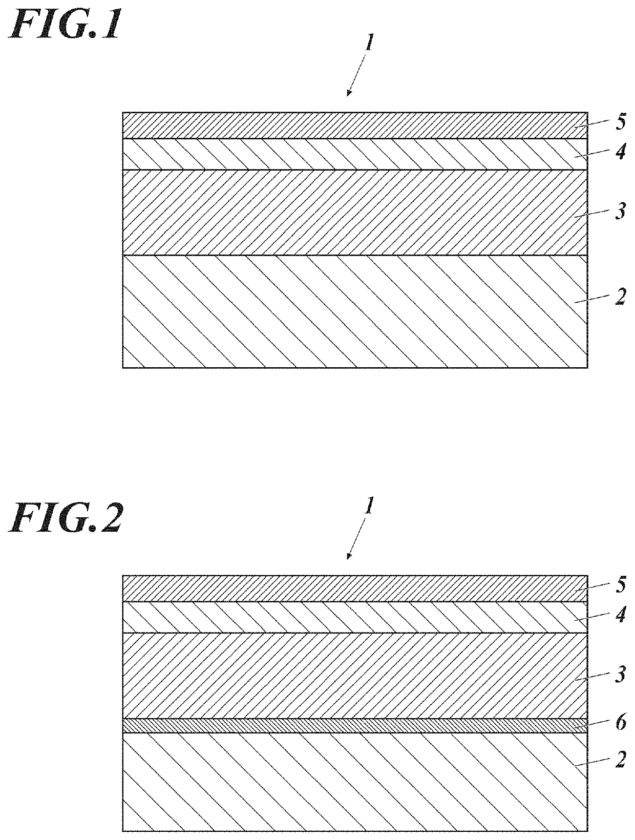
[0148]A nozzle plate 1 constituted by the substrate 2, the base layer 3, the intermediate layer 4, and the liquid repellent layer 5 shown in FIG. 1 was produced according to the following method.

[0149](1) Preparation of Substrate

[0150]A stainless steel substrate (SUS 304) of 3 cm in length, 8 cm in width and 50 μm in thickness without surface treatment was used as a substrate. The maximum height Rz of the stainless steel substrate was measured by means of a non-contact type three dimension microscopic surface configuration measuring system RSTPLUS produced by WYKO Corporation in conformity with JIS B 0...


PUM

PropertyMeasurementUnit
thicknessaaaaaaaaaa
structureaaaaaaaaaa
thicknessaaaaaaaaaa

Abstract

A nozzle plate includes, on a substrate: at least a base layer; an intermediate layer; and a liquid repellent layer. The base layer contains a silane coupling agent A having reactive functional groups at both terminals and including a hydrocarbon chain and a benzene ring at an intermediate part. The intermediate layer contains an inorganic oxide. The liquid repellent layer contains a fluorine (F)-containing coupling agent B.

Description

TECHNICAL FIELD[0001]The present invention relates to a nozzle plate, a nozzle plate manufacturing method, and an inkjet head. More specifically, the present invention relates to a nozzle plate exhibiting excellent liquid abrasion resistance, alkali ink resistance, liquid repellency on the surface of the nozzle plate when ink is jetted; a manufacturing method for the nozzle plate; and an inkjet head provided with the nozzle plate.BACKGROUND ART[0002]The inkjet recording apparatus, which is widely used at present, holds an inkjet head having a nozzle plate in which a plurality of nozzle holes are formed in rows in a frame by attaching it to a frame, and ejects ink from the plurality of nozzles toward the recording medium in a state of minute droplets, thereby forming an image on the recording medium.[0003]As a typical ink ejection method for an inkjet head, there are a method in which water in ink is vaporized and expanded by heat generated by passing a current through an electric re...

Claims


Application Information

Patent Timeline
Patent Type & Authority Applications(United States)
IPC IPC(8): B41J2/14B41J2/16
CPCB41J2/1433B41J2/162B41J2/164B41J2202/03B41J2/1642B41J2/1645B41J2/1646B41J2/1643
Inventor YAMADA, AKIHISA
Owner KONICA MINOLTA INC
Why Eureka
Try Eureka