
Method for operating a brushless and sensorless multi-phase electric motor, and drive device with an electric motor

a multi-phase electric motor and sensorless technology, applied in the direction of dynamo-electric converter control, dynamo-electric gear control, dynamo-electric brake control, etc., can solve the problem of limited flux-based sensorless measurement methods, low cost and low accuracy of rotary sensors or encoders

Pending Publication Date: 2022-08-04
BROSE FAHRZEUGTEILE SE & CO KGAA WUERZBURG
View PDF4 Cites 0 Cited by
  • Summary
  • Abstract
  • Description
  • Claims
  • Application Information

AI Technical Summary

Benefits of technology

The invention provides a method for operating a brushless and sensorless multiphase electric motor that overcomes the disadvantages of existing devices. The method allows for effective and reliable operation at low or standstill speeds. This invention also includes an electric drive that utilizes this new method.

Problems solved by technology

However, rotary sensors or encoders of this kind are costly, for which reason position determination should preferably be carried out without sensors.
The induced back-EMF signals are proportional to the rotational speed of the rotor, as a result of which, disadvantageously, only little or no information about the position determination is available for motor control at low rotational speeds or at a standstill of the electric motor.
There is also a limitation of this kind for flux-based sensorless measurement methods.
As a result, position determination or position identification below a threshold rotational speed is generally not possible, as a result of which safe and reliable operation of the electric motor, in particular during start-up from standstill or during operation at a low rotational speed, is disadvantageously made difficult.
It is a disadvantage that the method requires relatively high motor or phase currents.
Furthermore, the electric motor or the rotor is accelerated relatively slowly so that a long starting or start-up time is provided.
There is also the risk of oscillations and the loss of the synchronous field.
As a disadvantage, the acoustics of a drive operated in such a way are also worsened by the oscillations and high motor currents.
However, disadvantageously, the method is able to be used only in drives that have corresponding properties, such as a sufficiently high dependence of the inductance on the rotor position, for example.
Moreover, the acoustic properties of the electric motor during operation are negatively influenced, as a result of which increased noise emission is produced.

Method used


Image

  • Method for operating a brushless and sensorless multi-phase electric motor, and drive device with an electric motor
  • Method for operating a brushless and sensorless multi-phase electric motor, and drive device with an electric motor
  • Method for operating a brushless and sensorless multi-phase electric motor, and drive device with an electric motor

Examples


Embodiment Construction

[0075]Mutually corresponding parts and variables are provided with the same reference signs throughout the figures.

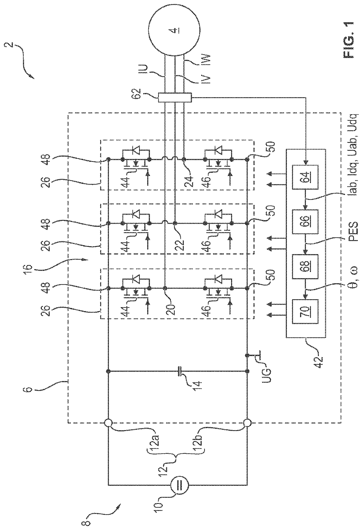
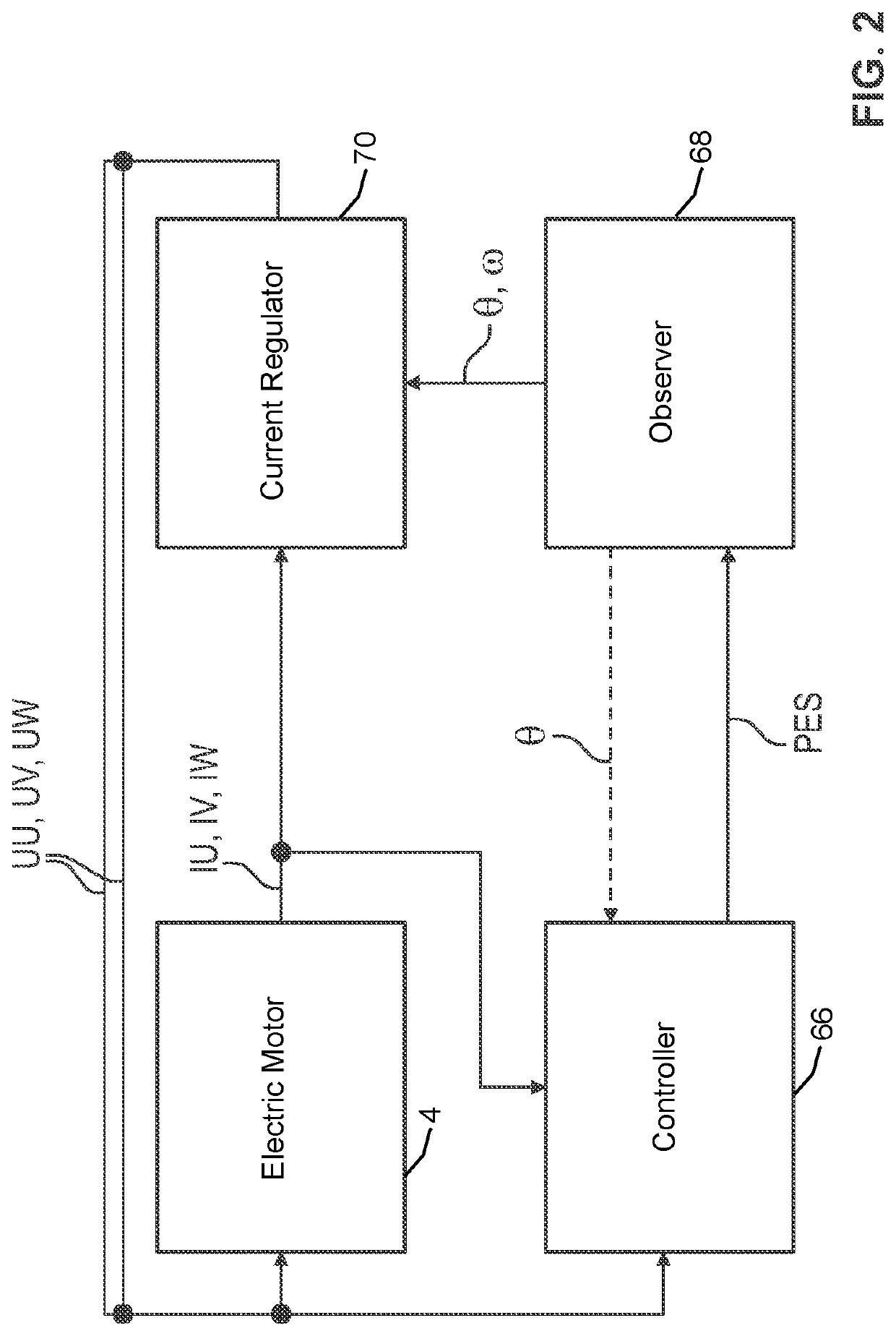
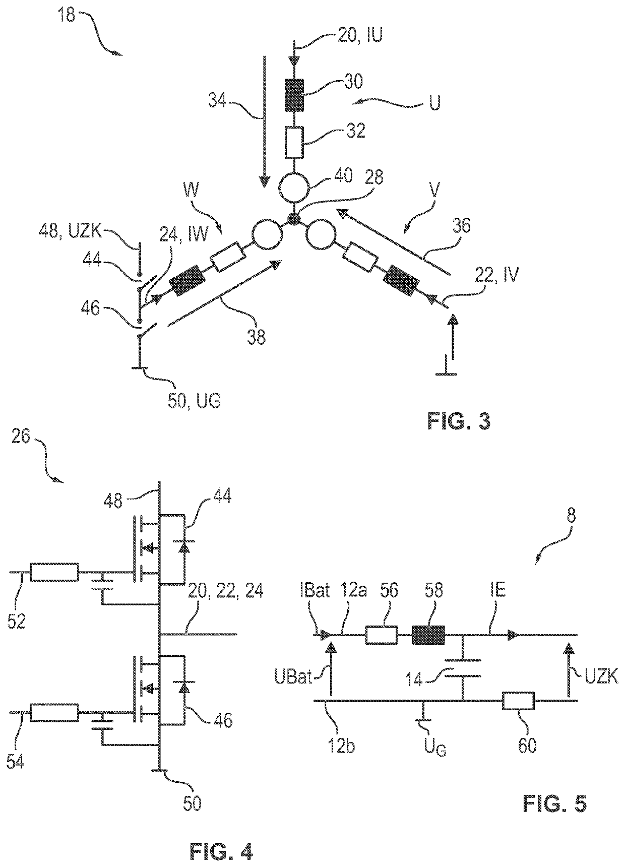
[0076]FIG. 1 shows an electric or electromotive drive 2 for an adjustment system of a motor vehicle, for example a window lifter or a seat adjustment system. The drive 2 comprises a brushless and sensorless three-phase electric motor 4, which is connected to a current source (voltage supply) 8 by way of a power converter 6. In this exemplary embodiment, the current source 8 comprises a vehicle-internal energy storage device 10, for example in the form of a (motor vehicle) battery, and a (DC) intermediate circuit 12, which is connected to said energy storage device and which extends at least partly into the power converter 6.

[0077]The intermediate circuit 12 is essentially formed by an outgoing line 12a and a return line 12b, by means of which the power converter 6 is connected to the energy storage device 10. The lines 12a and 12b are fed at least partly into the power ...


PUM


Abstract

A method for operating a brushless and sensorless multi-phase electric motor. At least two phase voltages and at least two phase currents of the electric motor are determined. A voltage vector is determined from the phase voltages and / or a current vector is determined from the phase currents. A position substitute signal is determined as a measure of a rotor position on the basis of an angle of the current vector and / or of the voltage vector. A rotation value is calculated on the basis of the position substitute signals, and the electric motor is controlled by open-loop and / or closed-loop technology on a basis of the rotation value.

Description

CROSS-REFERENCE TO RELATED APPLICATION[0001]This application is a continuation, under 35 U.S.C. § 120, of copending International Patent Application PCT / EP2020 / 078677, filed Oct. 13, 2020, which designated the United States; this application also claims the priority, under 35 U.S.C. § 119, of German Patent Application DE 10 2019 215 853.6, filed Oct. 15, 2019; the prior applications are herewith incorporated by reference in their entirety.FIELD AND BACKGROUND OF THE INVENTION[0002]The invention relates to a method for operating a brushless and sensorless multiphase electric motor. The invention furthermore relates to an electric drive, in particular for an adjustment element (adjustment system) of a motor vehicle, having an electric motor operated in accordance with the method.[0003]Adjustment systems operated or driven by electric motors, as motor vehicle components, such as for example window lifters, seat adjustment systems, door and sunroof drives or cooling fan drives, as well ...

Claims


Application Information

Patent Timeline
Patent Type & Authority Applications(United States)
IPC IPC(8): H02P21/09H02P21/13
CPCH02P21/09H02P21/13H02P6/18H02P21/24H02P2207/05
Inventor SCHWARZKOPF, JOHANNES
Owner BROSE FAHRZEUGTEILE SE & CO KGAA WUERZBURG
Learn More