
Invisible coated infrared patterns

a technology of infrared pattern and coating, which is applied in the direction of electromagnetic radiation sensing, instruments, and sensing record carriers, etc., can solve the problem that infrared pattern is not detectable under standard lighting conditions

Pending Publication Date: 2022-07-28
NEC CORPOATION OF AMERICA
View PDF23 Cites 0 Cited by
  • Summary
  • Abstract
  • Description
  • Claims
  • Application Information

AI Technical Summary

Benefits of technology

The patent describes a method for protecting infrared patterns on articles from damage caused by abrasion, organic solvents, moisture, and sunlight using a coating. The coating can be made of materials such as paper, plastic, or ink that can provide penetrability to infrared radiation and partial opacity in the visible range. The method also includes enhancing the infrared pattern with contrast enhancement and edge sharpening using an infrared imaging device. The method improves the resolution of the imaged pattern and makes it easier to read the code formed from the pattern. The method may involve sequentially projecting infrared radiation or visible illumination onto the article and comparing the resulting images to improve pattern sharpness. Overall, the patent provides a protective and enhanced method for creating infrared patterns.

Problems solved by technology

However, the opacity of the coating to visible radiation is sufficient that the infrared pattern is not detectable under standard lighting conditions.

Method used


Image

  • Invisible coated infrared patterns
  • Invisible coated infrared patterns
  • Invisible coated infrared patterns

Examples


examples

[0063]The principles elucidated above were implemented in the following, non-limiting examples.

[0064]Example 1: FIG. 4A depicts an image of uncovered infrared marker 414. Infrared marker 414 is made of infrared paint, and encodes an AprilTag™ code. Image 414 was obtained with an RGB camera, installed in a Samsung S9 Galaxy® smartphone, with an IR cut filter (hereinafter, “the smartphone camera”). The area was lit with ambient artificial fluorescent lighting. FIG. 4B depicts an image 430 of the same marker 414 imaged in the same artificial fluorescent lighting. A SiOnyx Aurora Sport™ RGB camera (hereinafter, the SiOnyx camera) was used, with the IR cut filter removed and an IR longpass filter introduced, having a cut-on wavelength (50% transmission) at 850 nm (hereinafter, an “850 nm longpass filter”). The AprilTag™ code is clearly visible.

[0065]Example 2: FIG. 5A depicts an image 550 of the same infrared marker of FIGS. 4A and 4B, covered by a piece of standard A4 printer paper. Ima...


PUM

PropertyMeasurementUnit
wavelengthsaaaaaaaaaa
transparentaaaaaaaaaa

Abstract

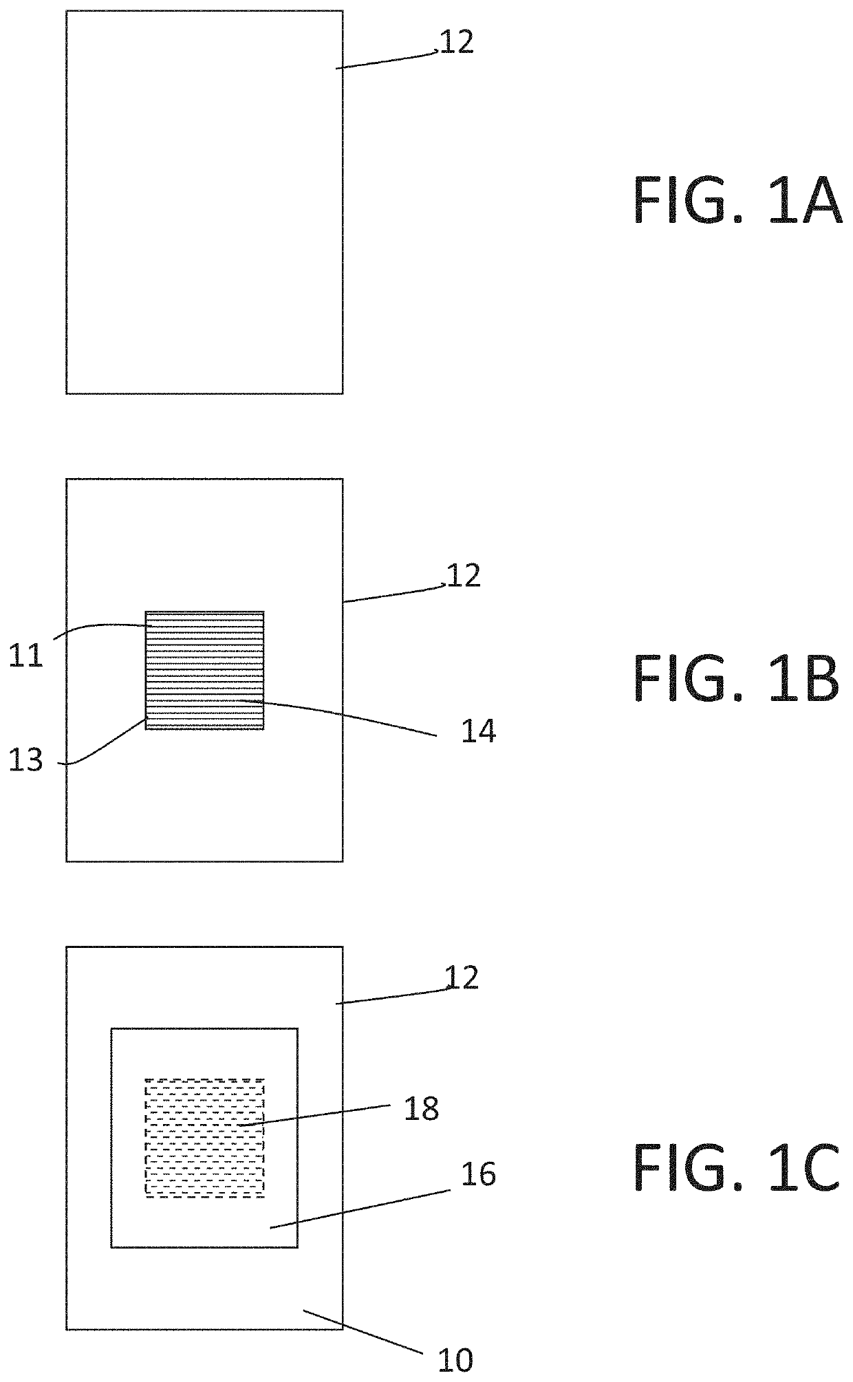
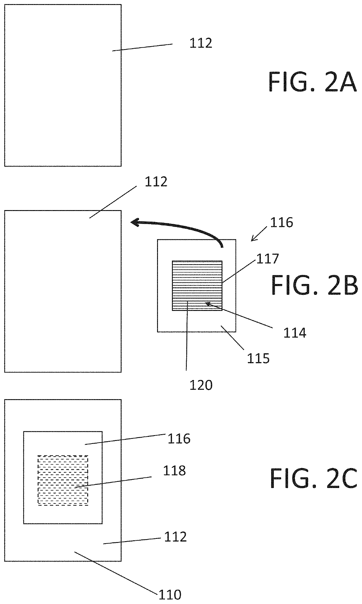
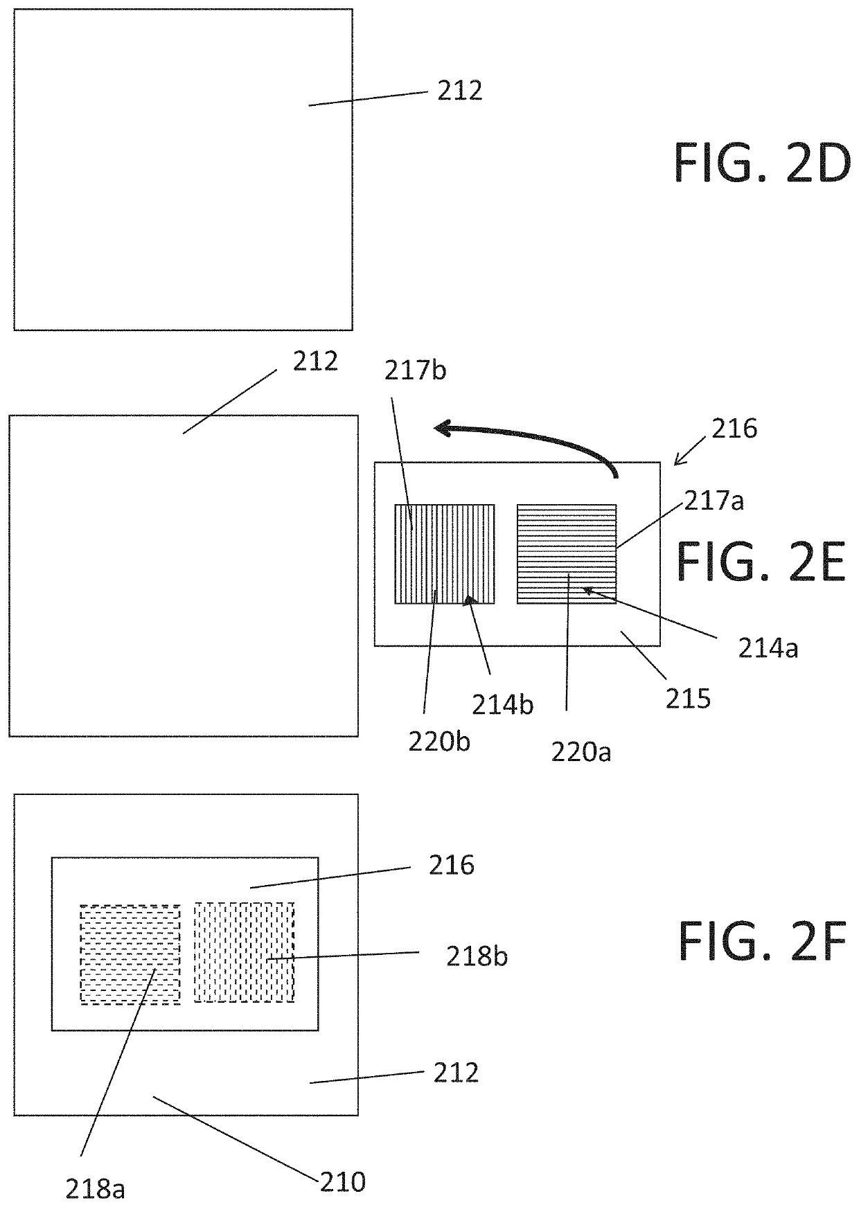
An article having an invisible infrared pattern is disclosed. The article includes at least one infrared pattern printed onto a surface. The infrared pattern includes regions of high absorption and high reflection for a plurality of wavelengths of infrared radiation ranging between 700 and 2000 nm. A coating is overlaid over the infrared pattern. The coating is made of a material and has a thickness that is penetrable by infrared radiation and that has an average opacity of at least 20 for light in the visible range.

Description

FIELD AND BACKGROUND OF THE INVENTION[0001]The present invention, in some embodiments, relates to an article having an invisible infrared pattern, and more specifically, but not exclusively, to an article including a coating overlaid over an infrared pattern, wherein the coating is made of a material and has a thickness that is penetrable by infrared radiation and is substantially opaque to light in the visible range.[0002]Visual machine codes or fiducial markers are two-dimensional binary patterns that are detectable using computer vision algorithms. Examples of such visual machine codes include Quick Response (QR) codes, AprilTag™ markers, and ArUCo™ markers. Visual machine codes are useful for product designation, product information, inventory management, and for detecting or proving location or pose. However, these codes may be visually unattractive and interfere with the visual design of an interior or exterior space.[0003]One solution for generating visual machine codes that ...

Claims


Application Information

Patent Timeline
Patent Type & Authority Applications(United States)
IPC IPC(8): G06K7/14G08C23/04G06K19/06
CPCG06K7/1404G06K19/06056G08C23/04G06K19/0614G06K1/123
Inventor LEV, TSVI
Owner NEC CORPOATION OF AMERICA
Learn More