
Optical sensor module

a technology of optical sensor module and lens holding member, which is applied in the direction of mounting, semiconductor devices, instruments, etc., can solve the problems of optical sensor module not being able to correctly receive light, the thickness of adhesive agent between the lens holding member and the substrate after the lens holding member is mounted thereon cannot be controlled, and the optical sensor module cannot receive light correctly

Pending Publication Date: 2022-07-28
MITSUBISHI ELECTRIC CORP
View PDF0 Cites 3 Cited by
  • Summary
  • Abstract
  • Description
  • Claims
  • Application Information

AI Technical Summary

Benefits of technology

This patent describes an optical sensor module that can be easily attached to an adhesive and prevent the lens holder from tilting. This helps to improve the accuracy and reliability of the optical sensor.

Problems solved by technology

However, in the conventional optical sensor module, the adhesive agent thickness between the lens holding member and the substrate after the lens holding member is mounted thereon cannot be controlled.
Therefore, in a case of performing adhesion using an apparatus not having an active alignment function that enables the lens holding member to be mounted while viewing an image acquired by operating the infrared detector, the lens holding member might be mounted in an inclined state with respect to the substrate, due to thickness variation of the adhesive agent, smallness of a load for mounting the lens holding member, imbalance of the position where the lens holding member is adhered, and the like.
As a result, there is a possibility that the focal point of the lens deviates from the light receiving portion of the infrared detector and thus the optical sensor module becomes unable to receive light correctly.
However, in particular, in a case where the lens is formed integrally with the lens holding member, if the lens holding member is inclined with respect to the infrared detector, there is a possibility that the focal point of the lens deviates from the light receiving portion of the infrared detector and thus light reception cannot be performed correctly.
Therefore, when the lens holding member is mounted on the adhesive agent, if the amount of the pasted adhesive agent is large or the load for mounting the lens holding member is great, the adhesive agent compressed by the lens holding member and thus wetting and spreading to the inner side of the lens holding member comes into contact with the wiring member on the inner side of the lens holding member.
The wiring member in contact with the adhesive agent is deformed to come into contact with the wiring member therearound or lead to breakage of a wire, thus causing such a risk that the infrared detector becomes unable to operate, for example.
However, in an optical sensor module having the lens and the lens holding member integrated with each other so as to reduce the size as compared to the general optical sensor module, the cost required for members can be reduced but it is impossible to correct the inclination of the lens after the lens holding member is adhered onto the substrate.
Moreover, operation failure due to contact between the adhesive agent and the wiring member cannot be inspected until the sensor is actually operated.
Therefore, the loss cost when failure occurs is greater than in the case of the general optical sensor module.

Method used


Image

  • Optical sensor module
  • Optical sensor module
  • Optical sensor module

Examples


embodiment 1

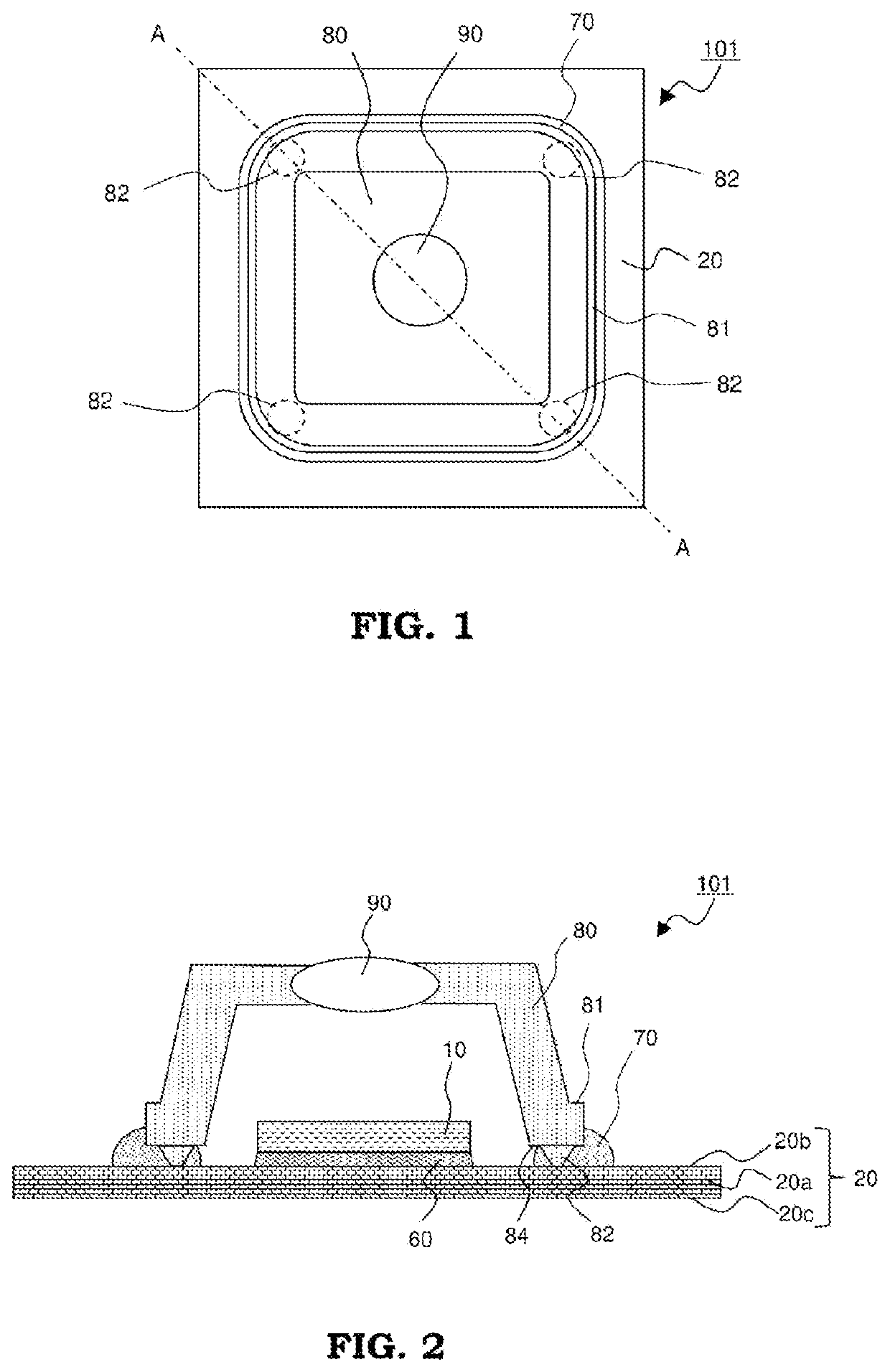
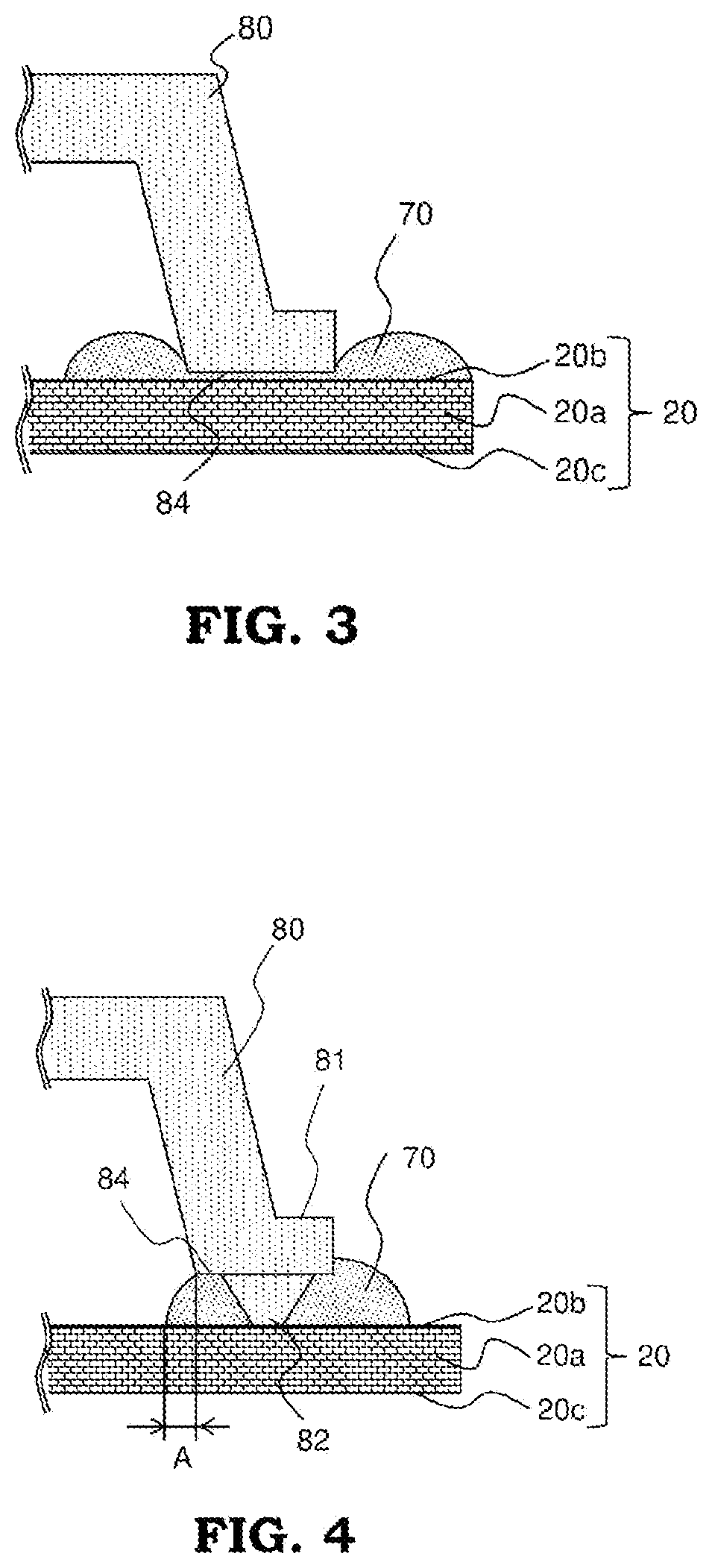
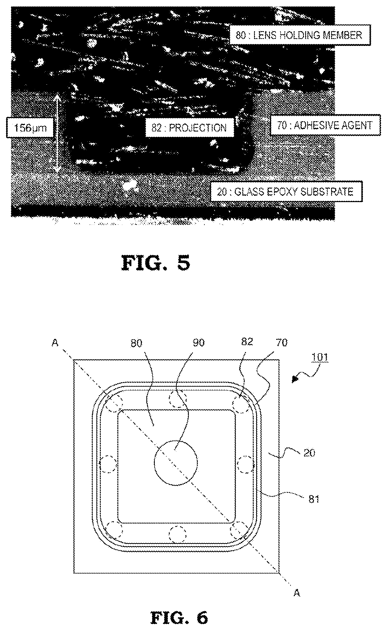
[0029]FIG. 1 is a plan view showing the schematic structure of an optical sensor module 101 according to embodiment 1, and FIG. 2 is a sectional view along line A-A in FIG. 1. The optical sensor module 101 includes, as basic components, an infrared detector 10 as a photodetector, a glass epoxy substrate 20 as a substrate, and a lens holding member 80 integrated with a lens 90 by inserting the lens 90 after molding and then caulking the periphery of the lens 90 with resin. The infrared detector 10 is adhered to one surface of the glass epoxy substrate 20 by Ag paste 60, and thus fixed and stored inside the lens holding member 80. The lens 90 for transmitting infrared rays therethrough and focusing the infrared rays is integrally fixed to the lens holding member 80, and a bottom surface 84 of the lens holding member 80 is adhered to the glass epoxy substrate 20 by an adhesive agent 70.

[0030]In FIG. 1 and FIG. 2, only basic constituent parts in the optical sensor module 101 are shown, ...

embodiment 2

[0057]FIG. 11 is a plan view showing the schematic structure of an optical sensor module 102 according to embodiment 2, and FIG. 12 is a sectional view along line A-A in FIG. 11. The optical sensor module 102 according to the present embodiment 2 basically has the same structure as the optical sensor module 101 according to embodiment 1, but has difference as described below. Here, the difference will be mainly described and description of the same constituent parts is omitted. FIG. 11 and FIG. 12 are schematic views showing only basic constituent parts in the optical sensor module 102, and description of the other constituent parts is omitted.

[0058]In embodiment 1, the infrared detector 10 is sealed by making the inside of the lens holding member 80 into a vacuum state after the entire periphery of the bottom surface 84 of the lens holding member 80 is adhered by the adhesive agent 70. On the other hand, in the present embodiment 2, as shown in FIG. 11 and FIG. 12, a light transmit...

embodiment 3

[0064]FIG. 13 is a plan view showing the schematic structure of an optical sensor module 103 according to embodiment 3, and FIG. 14 is a sectional view along line A-A in FIG. 13. Also the optical sensor module 103 according to the present embodiment 3 basically has the same structure as the optical sensor module 101 according to embodiment 1, but has difference as described below. Here, the difference will be mainly described and description of the same constituent parts is omitted. FIG. 13 and FIG. 14 are schematic views showing only basic constituent parts in the optical sensor module 103, and description of the other constituent parts is omitted.

[0065]In the present embodiment 3, as shown in FIG. 13 and FIG. 14, at the distal end of each projection 82 provided on the bottom surface 84 of the lens holding member 80, a positioning projection 82a extending in a truncated cone shape from the distal end of the projection 82 is formed integrally with the projection 82. A positioning ho...


PUM


Abstract

This optical sensor module includes: a substrate having an electrode pattern formed on a surface thereof; a photodetector for detecting light, the photodetector being electrically connected to the electrode pattern and being fixed to the substrate; and a lens holding member to which a lens is fixed, the lens holding member being adhered to the substrate by an adhesive agent at such a position as to surround the photodetector, wherein a bottom surface of the lens holding member adhered to the substrate has projections located in a distributed manner, and distal ends of the projections are in contact with the substrate.

Description

TECHNICAL FIELD[0001]The present disclosure relates to an optical sensor module.BACKGROUND ART[0002]Conventionally, an optical sensor module has been known which includes an infrared detector, a lens holding member storing the infrared detector, and a lens fixed to the lens holding member so as to be located forward of the infrared detector with the focal point of the lens overlapping a light receiving portion of the infrared detector.[0003]In the optical sensor module, for example, the lens holding member fixing and holding the lens is positioned relative to the infrared detector joined onto an insulating substrate such that the focal point of the lens overlaps the light receiving portion of the infrared detector. For this purpose, an adhesive agent (ultraviolet (UV) curable adhesive agent) is pasted in advance at a position where the bottom surface of the positioned lens holding member comes into contact with the insulating substrate, and then the lens holding member is mounted at...

Claims


Application Information

Patent Timeline
IPC IPC(8): G02B7/02H01L31/0203H01L31/0232
CPCG02B7/025H01L31/103H01L31/02325H01L31/0203H01L31/09
Inventor YONEDA, YUTAKA
Owner MITSUBISHI ELECTRIC CORP
Learn More