
Self-position estimation accuracy verification method and self-position estimation system

a self-position estimation and accuracy verification technology, applied in the field of self-position estimation accuracy verification method and self-position estimation system, can solve the problem that the accuracy of self-position estimation cannot be verified

Pending Publication Date: 2022-07-28
TOYOTA JIDOSHA KK
View PDF0 Cites 0 Cited by
  • Summary
  • Abstract
  • Description
  • Claims
  • Application Information

AI Technical Summary

Benefits of technology

The present disclosure provides a method and system for accurately estimating a mobile object's position. This is done by starting with a set of initial information and continuing to update it as the object moves. The accuracy of the position estimation is constantly verified based on the deviation between the verification information and a set of second check points, ensuring that the initial value is accurate and the position estimation is appropriate. This allows for reliable and accurate positioning of the mobile object.

Problems solved by technology

At the time of verification of the accuracy of the self-position estimation, there is a possibility that the accuracy of the initial values is sufficiently guaranteed and ignored, and the accuracy of the self-position estimation cannot be verified.

Method used


Image

  • Self-position estimation accuracy verification method and self-position estimation system
  • Self-position estimation accuracy verification method and self-position estimation system
  • Self-position estimation accuracy verification method and self-position estimation system

Examples


first embodiment

1. First Embodiment

[0030]1-1. Configuration of Vehicle System

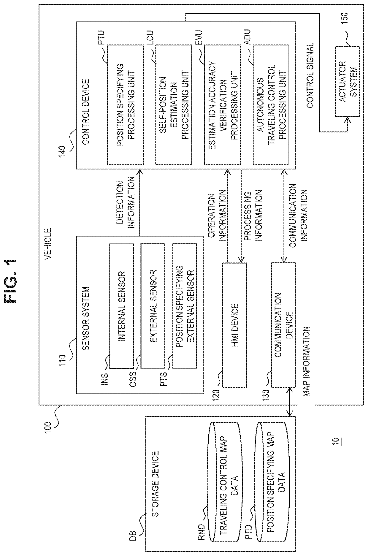
[0031]FIG. 1 is a block diagram used for describing a configuration of a vehicle system 10 according to a first embodiment. A vehicle system 10 according to the first embodiment includes a vehicle 100 and a storage device DB.

[0032]The vehicle 100 is an autonomously driving vehicle that can autonomously travel. The vehicle 100 includes a sensor system 110, an HMI device 120, a communication device 130, a control device 140, and an actuator system 150. The control device 140 constitutes a network so as to be capable of transferring information with each of the sensor system 110, the HMI device 120, the communication device 130, and the actuator system 150. Typically, the network is an in-vehicle network in which they are electrically connected to each other via a wire harness.

[0033]The sensor system 110 indicates a system of sensors that are provided in the vehicle 100, and detect and output various pieces of information nec...

second embodiment

2. Second Embodiment

[0096]Hereinafter, a second embodiment will be described. The already-described content above will be appropriately omitted.

[0097]2-1. Configuration of Vehicle System

[0098]In the second embodiment, the position of the vehicle 100 is specified by an external device. FIG. 8 is a block diagram used for describing a configuration of a vehicle system 10 according to the second embodiment. As illustrated in FIG. 8, in the second embodiment, the sensor system 110 of the vehicle 100 does not include the position specifying external sensor PTS, and the control device 140 does not include the position specifying processing unit PTU. On the other hand, the vehicle system 10 according to the second embodiment includes a position specifying device 200.

[0099]The position specifying device 200 is an external device that specifies the position of the vehicle 100. The position specifying device 200 is installed at each of a plurality of check points CP. Alternatively, the positio...


PUM


Abstract

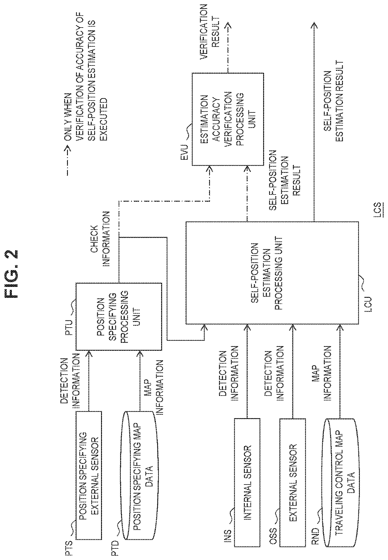
A self-position estimation accuracy verification method includes a step of moving a mobile object to a first check point, a step of acquiring first check information, a step of starting a self-position estimation using the first check information as an initial value, a step of moving the mobile object to a second check point while continuing the self-position estimation, a step of acquiring second check information, and a step of calculating a deviation between a position and a posture of the mobile object on the map estimated by the self-position estimation at the second check point and a position and a posture of the mobile object on the map indicated in the second check information, and verifying the accuracy of the self-position estimation based on the deviation.

Description

CROSS-REFERENCE TO RELATED APPLICATION[0001]This application claims priority to Japanese Patent Application No. 2021-012450 filed on Jan. 28, 2021, incorporated herein by reference in its entirety.BACKGROUND1. Technical Field[0002]The present disclosure relates to a self-position estimation accuracy verification method of verifying the accuracy of self-position estimation of a mobile object, and to a self-position estimation system.2. Description of Related Art[0003]WO 2018 / 061084 discloses a self-position estimation method that enhances the accuracy of self-position estimation by excluding target position data that is estimated to have many errors in terms of a relative position. The self-position estimation method includes detecting a relative position between a mobile object and a target present in the surroundings of the mobile object, accumulating a position where the relative position is moved by an amount by which the mobile object is moved as target position data, selecting ...

Claims


Application Information

Patent Timeline
IPC IPC(8): B60W50/02
CPCB60W50/0205B60W2050/0215G05D1/0214G05D1/0276G06T7/73G06T7/246G06T2207/30244G06T2207/30256G01C21/165G01C25/00G01C22/025
Inventor KAMIKADO, KAZUHIKOKAWANAI, TAICHIABE, SADAYUKIMATSUI, HIDEYUKI
Owner TOYOTA JIDOSHA KK
Learn More