Compact electromechanical brake

a brake and electromechanical technology, applied in the direction of braking systems, fluid actuated drum brakes, transportation and packaging, etc., can solve the problems of brake incorporating errors, unable to implement sensors in the actuator, and inability to accurately estimate the relative position of the brake mechanical elements at the end of the brake release phas

Pending Publication Date: 2022-07-28
HITACHI ASTEMO FRANCE
View PDF0 Cites 0 Cited by
  • Summary
  • Abstract
  • Description
  • Claims
  • Application Information

AI Technical Summary

Benefits of technology

The present invention provides an automobile vehicle brake that is compact and provides better control accuracy. The brake includes at least one electrically actuated component for applying braking force to a wheel. The actuator has a mechanical stop that helps determine the position of the brake with increased accuracy, which in turn allows for more accurate dimensions of the brake components. This results in a more compact brake design, faster brake application time, reduced noise and discomfort for drivers and passengers, and greater freedom in actuator dimensioning.

Problems solved by technology

No sensors are implemented in the actuator to know the relative position of the mechanical elements of the brake.
However, the estimation of the relative position of the mechanical elements of the brake at the end of the brake release phase is not very accurate.
As a result, the dimensioning of the brake incorporates these error and safety margins.
Furthermore, due to the inaccuracy in the position of the components in the released state, the starting position for the next braking operation is not known.
In addition, the stroke to be covered by the component(s) is lengthened which increases the brake application time, and also the time during which the actuator emits noise.

Method used


Image

  • Compact electromechanical brake
  • Compact electromechanical brake
  • Compact electromechanical brake

Examples


Embodiment Construction
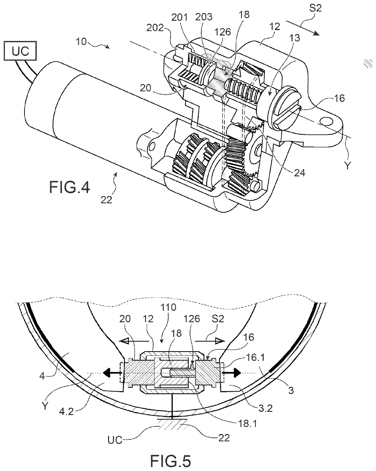
[0037]In FIG. 3, a “dual modedrum brake 2 in an exemplary embodiment of the invention can be seen.

[0038]The drum brake 1 includes a drum (not represented) movably integral with the wheel (not represented), an X-axis revolving backing plate 2 fitted with a first and a second arc-of-circle shoes 3 and 4, the shoes being radially movable so that they can be pressed against the cylindrical inner face of a drum not represented.

[0039]The shoes 3 and 4 each include a web 3a, 4a made of flat sheet in the form of a portion of a circular crown which carries a brake lining 3b, 4b, and are mounted diametrically opposite each other with their ends bearing on both a hydraulic wheel cylinder 6 and a mechanical actuator 10 carried by the backing plate 2. These shoes 3 and 4 are further biased towards each other by two return springs 8 and 9, and each pressed against the backing plate 2 by a so-called side spring.

[0040]A wear adjustment connecting rod 7 extends along the wheel cylinder 6, having a...


PUM


Abstract

An electromechanical drum brake comprises two brake segments intended to come into contact with a drum, and at least one actuator configured to apply the segments against the drum, and an electric motor configured to activate the actuator, the actuator comprising at least one member which is movable upon activation of the actuator, the movable member being movable between a braking position and a position beyond a release position, in which the segments are no longer in contact with the drum. The actuator comprises a stop which is arranged only in the actuator and against which the movable element bears when it assumes a position beyond the release position, and the motor powers the actuator until the movable element bears against the stop.

Description

BACKGROUND OF THE INVENTION[0001]The present invention relates to an at least partly electrically actuated automobile vehicle brake providing greater compactness.[0002]In most current automobiles, the service brake is provided by disc brakes and / or drum brakes.[0003]They perform the service braking function, which aims to slow down or even stop the automobile vehicle. The parking brake function aiming to bring a stationary vehicle to a standstill and the emergency brake function are usually achieved with the system providing the parking brake.[0004]The parking brake can be applied by pulling a lever arranged in the passenger compartment which is connected to a mechanism located in a drum brake or disc brake via a brake cable. The mechanism tends to move the braking shoes of the drum brakes apart to apply them against the drums. In the case of a disc brake, the brake pads are clamped to the brake disc.[0005]To improve driver comfort and safety in the application of the parking brake,...

Claims


Application Information

Patent Timeline
IPC IPC(8): B60T13/58B60T1/06B60T13/74F16D51/22F16D51/24F16D65/22
CPCB60T13/588B60T1/067B60T13/746F16D2127/02F16D51/24F16D65/22F16D51/22F16D65/14F16D65/09F16D2121/24F16D2121/04F16D2125/40F16D2125/48F16D2066/003F16D2066/006B60T13/745F16D2250/0084
Inventor WITTE, LENNARTDACLAT, JULIEN
Owner HITACHI ASTEMO FRANCE
Why Eureka
Try Eureka