
Inverter device

a technology of inverter and capacitor, which is applied in the direction of power conversion systems, control systems, electrical apparatus, etc., can solve the problems of electrolytic capacitor destruction, cost rise, upsizing, etc., and achieve the effect of shortening the time for warm-up operation, quick raising of the internal temperature and avoiding the destruction of the electrolytic capacitor

Active Publication Date: 2022-06-23
SANDEN CORP
View PDF6 Cites 0 Cited by
  • Summary
  • Abstract
  • Description
  • Claims
  • Application Information

AI Technical Summary

Benefits of technology

The present invention relates to an inverter device that can quickly warm up an electrolytic capacitor to a temperature within a safe range without damaging the capacitor. This is achieved by controlling the rate of increase in the current flowing through the electric motor using a control device. By changing the rate of increase in the current based on the input voltage and temperature detected by a temperature sensor, the device can safely and effectively raise the internal temperature of the electrolytic capacitor while suppressing the ripple voltage of the DC voltage within the permissible range. This reduces the time required for the warm-up operation and avoids the destruction of the capacitor in low-temperature environments.

Problems solved by technology

There is a risk that when an electrolytic capacitor is used under such an environment, an internal resistance component (equivalent series resistance) of the electrolytic capacitor rises to increase a ripple voltage, and the voltage applied to the electrolytic capacitor will exceed its breakdown voltage or become a reverse voltage, thus leading to its destruction.
A problem however arises in that costs rise and upsizing occurs.

Method used


Image

  • Inverter device
  • Inverter device
  • Inverter device

Examples


Embodiment Construction

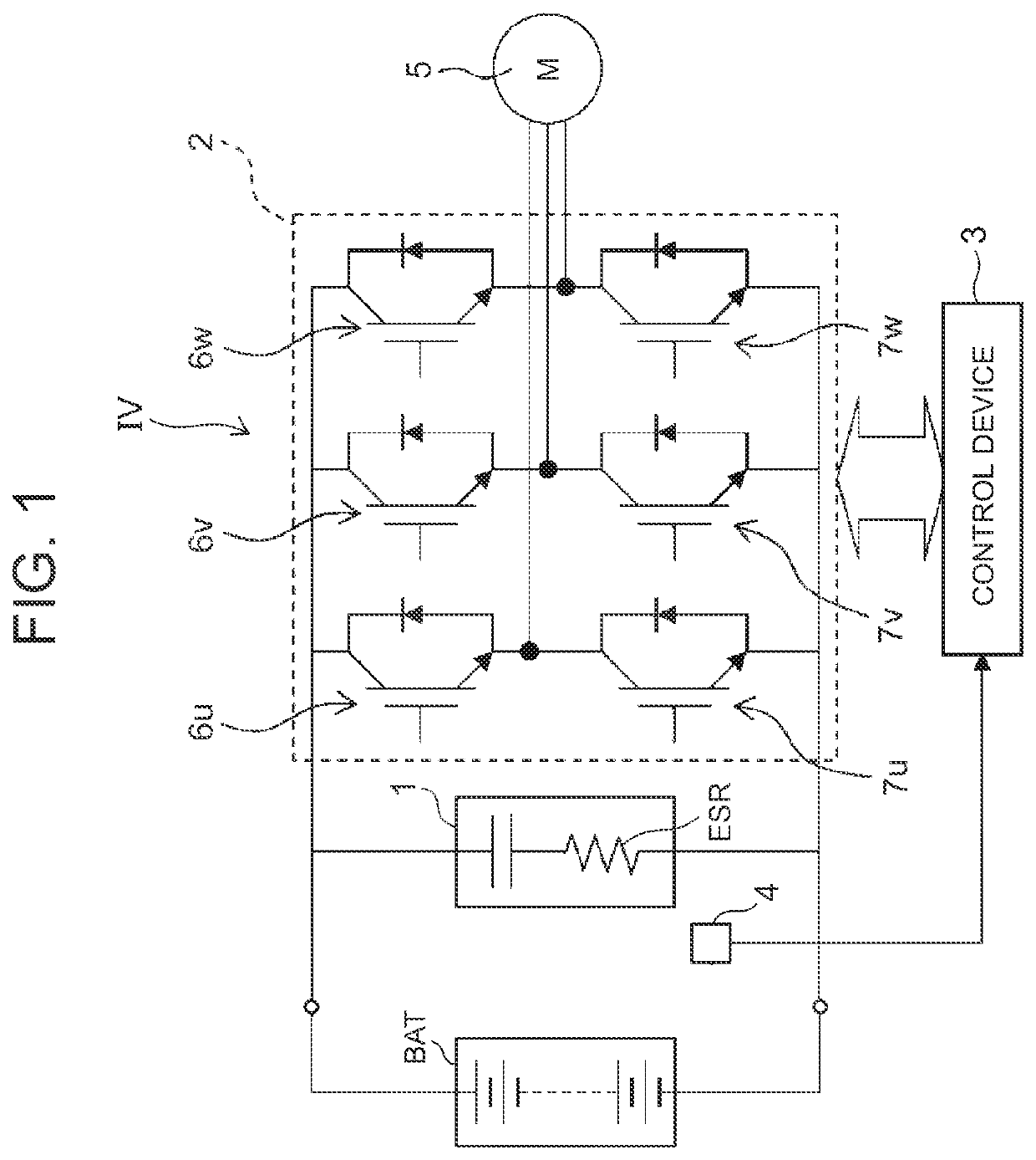
[0033]Hereinafter, embodiments of the present invention will be described in detail with reference to the drawings. FIG. 1 is an electric circuit diagram showing a schematic configuration of an inverter device IV of an embodiment to which the present invention is applied. The inverter device IV of the embodiment is an in-vehicle inverter device which is provided integrally with an unillustrated compressor constituting an air conditioning device for a vehicle and is mounted on the vehicle. The inverter device IV of the embodiment is that an input voltage HV from a battery (DC power supply) BAT mounted on the vehicle is smoothed by an electrolytic capacitor 1, and an AC voltage is generated from the smoothed DC voltage to drive a motor 5 as an electric motor. The inverter device IV is configured to include the electrolytic capacitor 1, an inverter circuit 2, a control device 3, and a temperature sensor 4.

[0034]The electrolytic capacitor 1 smooths the input voltage HV to a DC voltage, ...


PUM


Abstract

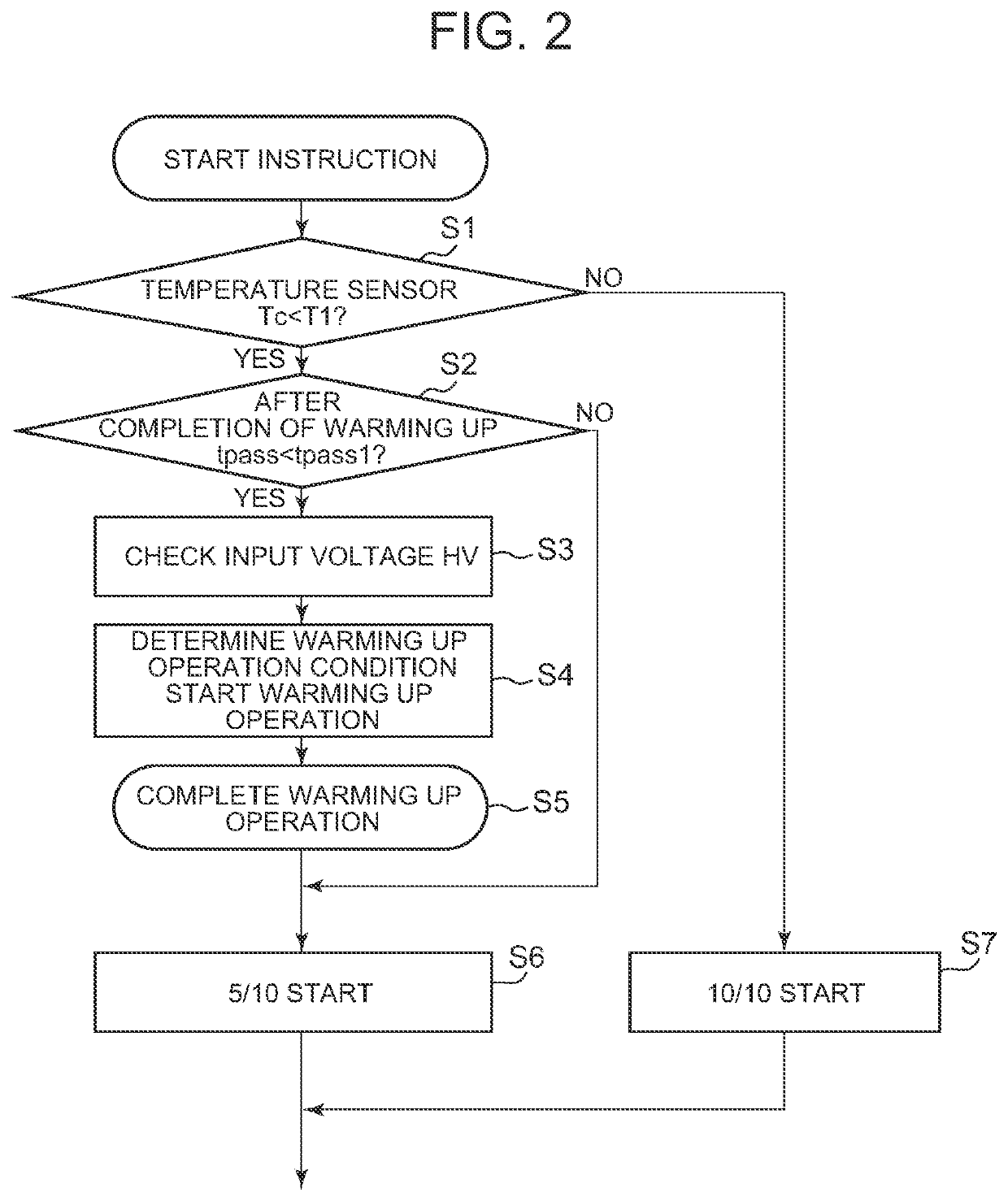
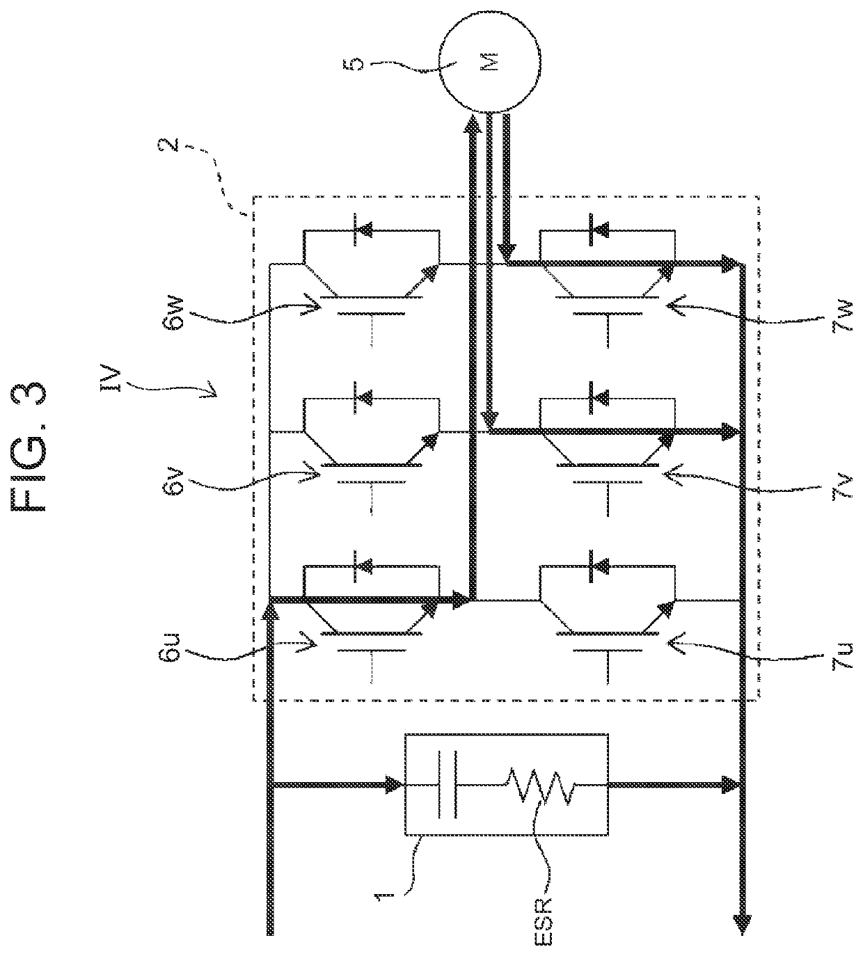
[Problem] An inverter device is provided which is capable of more quickly raising an internal temperature of an electrolytic capacitor within a permissible range of a ripple voltage to shorten a non-operating time. [Solution] The inverter device includes an electrolytic capacitor 1, an inverter circuit 2, a temperature sensor 4, and a control device 3. When the ambient temperature of the electrolytic capacitor 1 detected by the temperature sensor 4 is lower than a predetermined temperature, the control device 3 on-drives specific switching elements of the inverter circuit 2 before the start of a normal operation of a motor 5, and executes a warming up operation of allowing a current capable of controlling a ripple voltage of a DC voltage within a permissible range to flow through the motor 5 at a predetermined rate of increase while keeping the motor 5 stopped.

Description

CROSS-REFERENCE TO RELATED APPLICATIONS[0001]This application is a U.S. National Stage Patent Application under 35 U.S.C. § 371 of International Patent Application No. PCT / JP2020 / 016358, filed on Apr. 14, 2020, which claims the benefit of Japanese Patent Application No. 2019-087414, filed on May 7, 2019, the disclosures of each of which are incorporated herein by reference in their entirety.TECHNICAL FIELD[0002]The present invention relates to an inverter device which generates an AC voltage from a DC voltage smoothed by an electrolytic capacitor to drive an electric motor.BACKGROUND ART[0003]A conventional inverter device of this type selectively drives three switching elements on the upper phase side of an inverter circuit and three switching elements on the lower phase side thereof to thereby generate three-phase voltages of U, V, and W from a DC voltage to drive an electric motor. The inverter device is provided with an electrolytic capacitor which smooths a power supply voltage...

Claims


Application Information

Patent Timeline
Patent Type & Authority Applications(United States)
IPC IPC(8): H02M7/5387H02P27/08H02M1/14H02P29/68
CPCH02M7/5387H02P29/68H02M1/14H02P27/08H02P29/62H02M7/5395H02M1/36H02M1/327
Inventor MAKIMURA, YUKIMATSUDA, MASATAKAFUJISAKI, SHOGOSAITO, MASATOSHI
Owner SANDEN CORP
Learn More