Battery simulator having compensation impedance

Pending Publication Date: 2022-06-23
KRISTL SEIBT
View PDF0 Cites 0 Cited by
  • Summary
  • Abstract
  • Description
  • Claims
  • Application Information

AI Technical Summary

Benefits of technology

The present invention aims to improve the testing of electrical items by minimizing the deviation between the actual voltage provided to the item and the voltage specified by the simulation model, even at high switching frequencies. This is achieved by providing an adjustable resistor and / or an adjustable capacitor that can compensate for changes in the simulation model or other influences, such as temperature fluctuations. These compensation elements can be adjusted mechanically or electronically, and can be controlled manually or automatically. Overall, the invention enhances the accuracy and reliability of testing electrical items.

Problems solved by technology

However, the time required to bring the battery into the desired state (state of charge, temperature, ageing, etc.) before each test, would be enormous, and would not always be reliably reproducible.
However, it is problematic that, especially at high switching frequencies, the voltage actually provided to the test item sometimes deviates considerably from the voltage specified by the simulation model, and high-frequency voltage fluctuations can occur.
This can lead to the test item switching off due to over- or undervoltage, or to the test item being damaged.
Compensation of this deviation by means of the simulation model has not yet been possible, not least because of the increase in voltage through the simulation unit theoretically necessary for this purpose.
Tests on fast-switching test items can therefore not be carried out reliably.
As described above, this leads to problems, especially at high frequencies, because the impedance of the simulation unit is not presented to the test item as actually desired, but rather the increased source impedance.

Method used


Image

  • Battery simulator having compensation impedance
  • Battery simulator having compensation impedance

Examples


Embodiment Construction

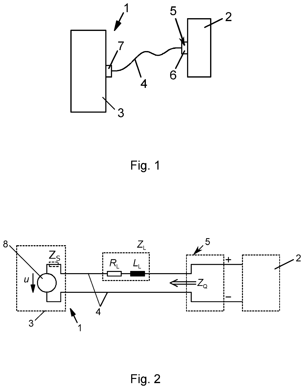
[0035]FIG. 1 shows a simplified representation of the device 1 in accordance with the invention, to which is connected a test item 2 in the form of an electric drive unit. The device 1 has a simulation unit 3 for the simulation of an electrical energy storage, for example a battery or an accumulator, and an electrical connecting line 4, at the end of which is located a connecting unit 5, with a plug and / or coupling unit 6. However, screw terminals can also be provided on the connecting unit 5. The plug and / or coupling unit 6 is connected to the test item 2, and establishes an electrical connection between the test item 2 and the simulation unit 3.

[0036]The simulation unit 3 can be formed by a computer or a microprocessor, and can provide a current and a voltage in accordance with a simulation model by way of an output 7. Current and voltage are transferred to the test item 2 by way of the connecting line 4. The simulation unit 3 thus essentially corresponds to a feedforward controll...


PUM


Abstract

The invention relates to a device for testing, in particular high-frequency testing, a test item, for example an electrical machine or a converter, comprising:a simulation unit for simulating an electrical energy accumulator using a simulation model; andan electrical connection line, via which the test item can be connected to the simulation unit; wherein the device comprises compensation impedance for compensating for an impedance in accordance with a line inductance of the connection line.

Description

TECHNICAL FIELD[0001]The invention relates to a device for the testing, in particular the high-frequency testing, of a test item, for example of an electrical machine or a converter, having:[0002]a simulation unit for the simulation of an electrical energy storage with the aid of a simulation model, and[0003]an electrical connecting line, by way of which the test item can be connected to the simulation unit.BACKGROUND AND SUMMARY[0004]The invention furthermore relates to a method for the testing, in particular the high-frequency testing, of a test item, for example of an electrical machine or a converter, in which the test item is connected to a simulation unit by way of an electrical connecting line, wherein the simulation unit simulates an electrical energy storage with the aid of a simulation model.[0005]The voltage of an energy storage, such as a battery or an accumulator, is not constant, but depends on the profile of the present and past current flow, on the state of charge, t...

Claims


Application Information

Patent Timeline
IPC IPC(8): G01R31/367G01R31/385G01R31/388G01R31/389
CPCG01R31/367G01R31/389G01R31/388G01R31/3865G01R31/00G01R31/3183G01R31/42G01R31/2846
Inventor HAIDINGER, THOMASGOELDNER, ARTHURAUER, CHRISTIAN
Owner KRISTL SEIBT
Why Eureka
Try Eureka