Stent device for a prosthetic heart valve

Pending Publication Date: 2022-06-09
T HEART SAS
View PDF0 Cites 0 Cited by
  • Summary
  • Abstract
  • Description
  • Claims
  • Application Information

AI Technical Summary

Benefits of technology

The patent describes a stent device that has a mesh-shaped structure made up of polygons or cells that are connected to each other or via struts. The mesh-shaped structure can be formed as a lattice or a plurality of polygons arranged in an axial direction to form a honeycomb structure. The stent device is made from a single piece and has high structural and mechanical stability. The technical effects of this patent include improved structural integrity, reduced breakage, dislodgement, and production errors, and increased stability of the stent device.

Problems solved by technology

Such sealing efficiency may be impaired due to various pathological conditions, e.g. due to a functional pathology of the tricuspid valve, which pathology may be elusive, severe, and secondary to a significant dilation of the tricuspid annulus.
A dysfunctional tricuspid valve may lead to tricuspid regurgitation, which is a common medical problem and is associated with significant challenges.
For example, patients suffering from tricuspid regurgitation generally suffer from a chronically disfunctional fluid retention and have a low cardiac output.
Furthermore, the annulus diameter may extend over 40 mm, such that anatomic landmarks between the right ventricle and right atrium are gradually lost, thereby impairing and complicating treatment, repair and replacement of the tricuspid valve.
However, such systems and techniques are primarily aimed at replacement of the mitral valve, which are not directly applicable to a replacement of the tricuspid valve.
Said differences directly affect both the mechanical stability and the propensity for peri-prosthetic leaks, such that—in contrast to assertions in the literature—mitral valve replacement techniques are typically not applicable to the tricuspid valve.
Tricuspid valve replacement is also intricate, as that body site lacks generally body tissue volume holding a prosthetic device in place.
Alternative fixation-based techniques using the leaflets of the tricuspid valve are only adapted to a limited portion of the tricuspid valve while at the same time requiring a profile height of more than 30 mm, which is bulky, may increase the risk of dislodgement, and may impair blood flow.
Such arrangement exhibits limited support of and adaptability to the anatomical structures of the tricuspid valve and requires a clamping of the native leaflets, which may be detrimental for the remaining anatomical landmarks.

Method used


Image

  • Stent device for a prosthetic heart valve
  • Stent device for a prosthetic heart valve
  • Stent device for a prosthetic heart valve

Examples


Embodiment Construction

[0102]In the following, the invention will be explained in more detail with reference to the accompanying figures. In the Figures, corresponding elements are denoted by identical reference numerals and repeated description thereof may be omitted in order to avoid redundancies.

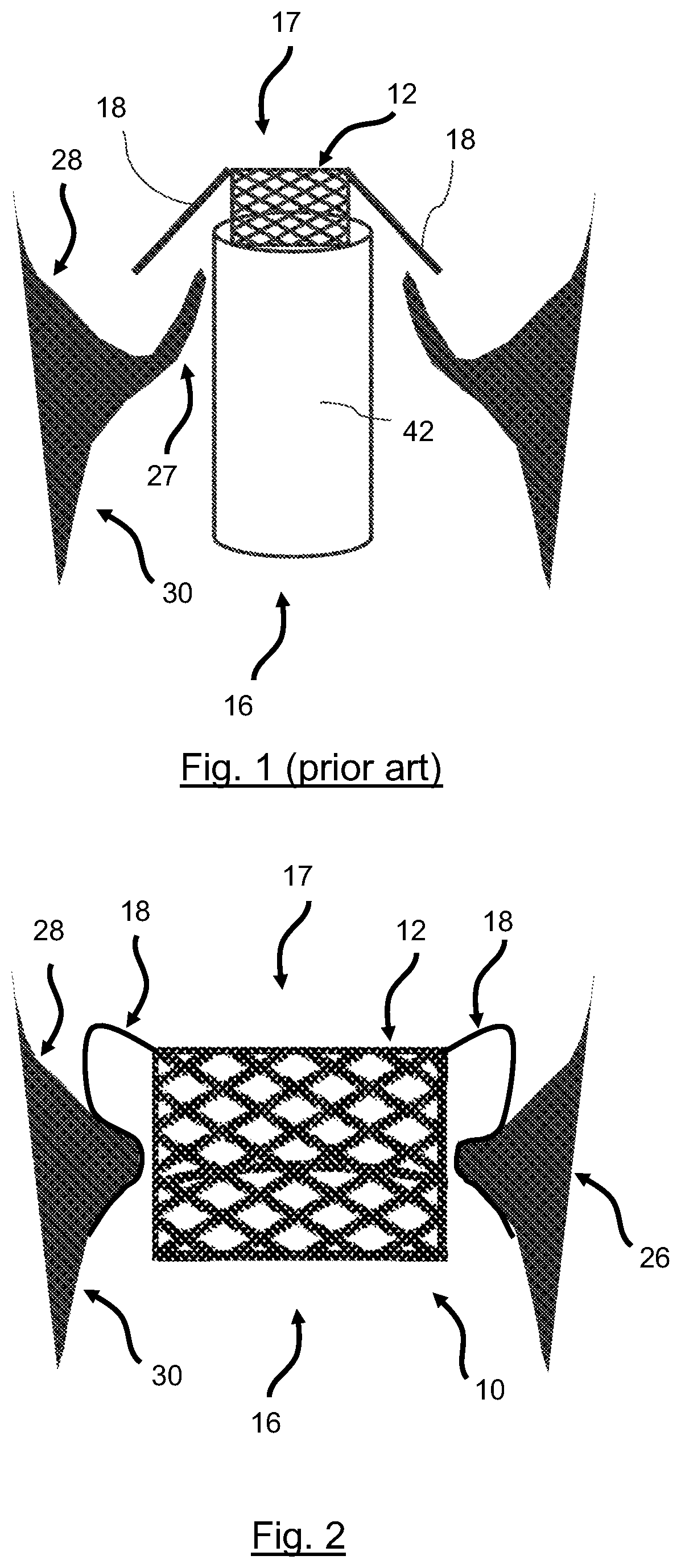
[0103]In FIG. 1 a graphical representation of a prior art embodiment of a prosthetic heart valve positioned within a tricuspid valve is shown. Accordingly, a prosthetic heart valve is positioned within the tricuspid valve by means of a delivery system 42, e.g. a catheter or sheath. The prosthetic heart valve is positioned such that the body 12 or framework of the prosthetic heart valve is oriented in a longitudinal direction from a proximal end 16 to a distal end 17 of the tricuspid valve. Accordingly, upon deployment or expansion of the prosthetic heart valve, the support arms 18 of the prosthetic heart valve grasp the leaflets 27 of the tricuspid valve, thereby forming ventricular stabilizers. The support arm...


PUM


Abstract

Replacing a defective atrioventricular heart valve, in particular a tricuspid valve, may include stent devices, prosthetic heart valves, delivery systems, and corresponding methods, which provide an improved fixation without distortion of the native anatomy. A stent device for a prosthetic heart valve has an axially extending mesh-shaped body, configured to fit an orifice and defining an inner channel as a passageway from a proximal to a distal end. At least three outer support arms extend from the distal end of the body towards the proximal end. Each support arm has a distal end first support region and a proximal end second support region. The second support region extends radially outwards in the deployed state. Each support arm has a flexible region between the first and second support regions, which is formed as an axially tapered section of the support arm and / or each support arm is tapered towards the proximal end.

Description

CROSS-REFERENCE TO RELATED APPLICATIONS[0001]This application is the U.S. National Stage of PCT / EP2020 / 063739 filed May 15, 2020, which claims priority to PCT Patent Application No. PCT / EP2019 / 062842, filed May 17, 2019, the content of both are incorporated herein by reference in their entirety.FIELD OF THE INVENTION[0002]The invention relates to the field of replacing a defective atrioventricular heart valve, in particular a tricuspid valve, including stent devices, prosthetic heart valves, and delivery systems, as well as methods for producing such stent device and methods for replacing a tricuspid valve or mitral valve using such stent device.BACKGROUND OF THE INVENTION[0003]The blood circulation in mammals is primarily driven by the pumping function of the heart. Such cardiac function is provided not only to ensure that tissue is sufficiently perfused, but also to provide a de-carbonization and re-oxygenation of effluent blood after passing tissue. The human heart comprises two ...

Claims


Application Information

Patent Timeline
IPC IPC(8): A61F2/24
CPCA61F2/2418A61F2/2415A61F2230/0069A61F2002/9505A61F2230/0056A61F2230/0008A61F2230/005A61F2210/0014A61F2230/0093
Inventor DIBIE, ALAINEL GHAZOUANI, SOAD
Owner T HEART SAS
Why Eureka
Try Eureka