Conductive plane damper

Pending Publication Date: 2022-05-26
ZHU DAYUN
View PDF0 Cites 0 Cited by
  • Summary
  • Abstract
  • Description
  • Claims
  • Application Information

AI Technical Summary

Benefits of technology

The present invention provides a conductive plane damper that allows for electrical conduction without the need for a lead wire, reducing the thickness of a speaker. The damper has voice coil welding points on the inner circle and wire welding points on the outer circle, allowing for direct connection between the voice coil and power supply wire. Cables are installed at the wire welding points of the outer circle, reducing the likelihood of cable breakage and extending the life of the product. The wire welding points are arranged in the outer circle to optimize production. Overall, the conductive plane damper improves the quality and reliability of speakers while reducing their size.

Problems solved by technology

When the horn sounds out, the wire and the damper resonate so as to beat up and down, forming a rope skipping phenomenon, affecting the vibration of the damper, resulting in sound distortion, affecting the sound effect of the speaker.
However, the existing damper can not adjust the the amplitude of the beating, and needs to be improved.
Although the Chinese patent CN201820724500.3 addresses the sound distortion of the damper caused by cables, the supporting boxes, the universal bearings and the limiting plate increase the thickness of the damper, which also make the speaker more weight and occupy large space, and the cable is easy to break, and the structure is very complex.
The installation process is more complex and the cable is easy to break as the vibration of the damper.

Method used


Image

  • Conductive plane damper
  • Conductive plane damper

Examples


Embodiment Construction

[0022]In order to make the objects, the technical solutions and the technical effect of the present invention are more clear, and the present invention is further explained below in combination with specific embodiments. It should be understood that the specific embodiments described herein are used only for interpreting the invention and are not used to define the invention.

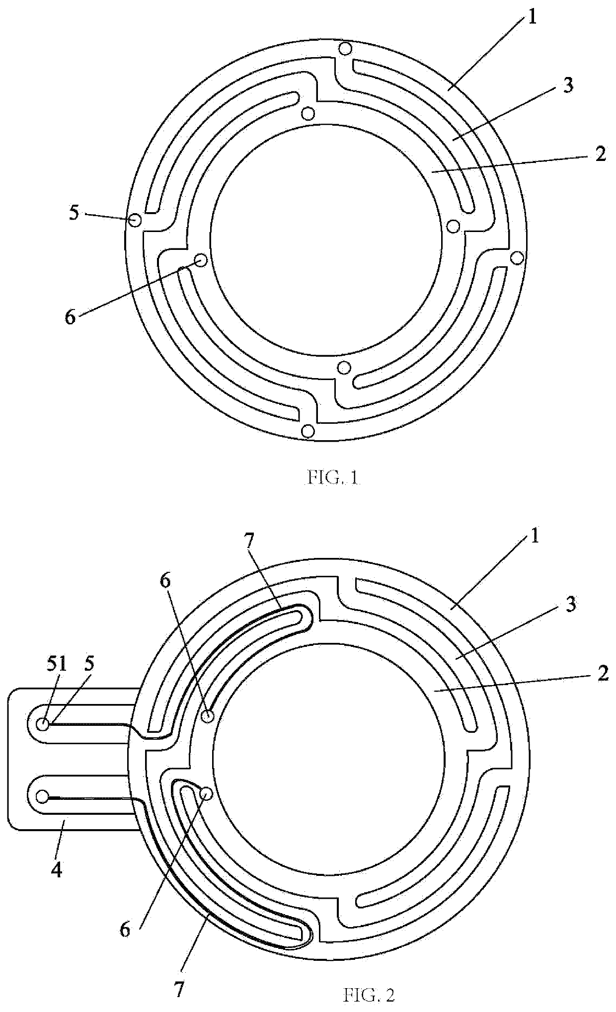
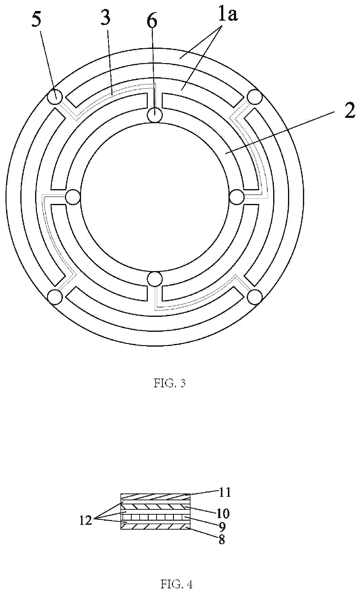
[0023]Referring to FIGS. 1, 2 and 3, a conductive plane damper includes an outer circle 1, an inner circle 2 and several connecting parts 3. The inner circle 2 lies in the outer circle 1, several connecting parts 3 are evenly distributed between the outer circle 1 and the inner circle 2, and a head end and a tail end of each of the connecting parts 3 are respectively fixedly connect with the outer circle 1 and the inner circle 2. With these hollow-out structure, the thickness and weight of the conductive plane damper are greatly reduced, and the traditional damper structure that requires concave and convex lines...


PUM


Abstract

The invention discloses a conductive plane damper, which includes an outer circle, an inner circle and several connecting parts; several the connecting parts are evenly distributed between the outer circle and the inner circle, connecting the outer circle and the inner circle; the conductive plane damper are provided with at least two pairs of voice coil welding points and wire welding points; the voice coil welding points are arranged on the inner circle, the wire welding points are arranged on the outer circle. The speaker with the conductive plane damper avoids the usage of the lead wire and the speaker losing sound because of breaking of the lead wire, thereby greatly reducing the thickness of the conductive plane damper and increasing the quality of the speakers.

Description

FIELD OF THE INVENTION[0001]The present invention relates to speaker technical field, more particularly, to a kind of conductive plane damper.BACKGROUND OF THE INVENTION[0002]Loudspeaker generally includes a magnet, a U-yoke, a cone, a voice coil, a film and a damper etc. The damper, also named positioning bracket, is generally used for mounting the position of the voice coil so that the horn can ensure the vertical movement between the voice coil and the cone when shaking. In the prior art, the wire is often sewn directly on the damper. When the horn sounds out, the wire and the damper resonate so as to beat up and down, forming a rope skipping phenomenon, affecting the vibration of the damper, resulting in sound distortion, affecting the sound effect of the speaker. However, the existing damper can not adjust the the amplitude of the beating, and needs to be improved.[0003]Therefor, Chinese Patent CN201820724500.3 discloses a perforated wire damper, which includes a body. The body...

Claims


Application Information

Patent Timeline
IPC IPC(8): H04R7/10H04R7/20
CPCH04R7/10H04R2400/11H04R7/20H04R9/043H04R9/06H04R1/06
Inventor ZHU, DAYUN
Owner ZHU DAYUN
Why Eureka
Try Eureka