Eureka AIR delivers breakthrough ideas for toughest innovation challenges, trusted by R&D personnel around the world.

Method for estimating battery state of charge and battery management system applying the same

a battery and management system technology, applied in the direction of battery/fuel cell control arrangement, secondary cell servicing/maintenance, instruments, etc., can solve the problems of battery life reduction, battery state of charge and state of discharge, and battery maintenance performance loss, etc., to reduce the time of estimating a state of charge.

Pending Publication Date: 2022-05-19
LG ENERGY SOLUTION LTD
View PDF0 Cites 3 Cited by
  • Summary
  • Abstract
  • Description
  • Claims
  • Application Information

AI Technical Summary

Benefits of technology

The present invention provides a method for estimating the state of charge (SOC) of a battery system that includes multiple battery modules with multiple battery cells. This method reduces the time and memory space required for this estimation. By using this method, the battery system can estimate the state of charge of multiple batteries at once, which saves time and memory space. This results in a more efficient and effective battery management system.

Problems solved by technology

Therefore, the battery included in the electric vehicle may frequently cause transition of a state of charge and a state of discharge.
On the other hand, when the battery is connected to a load and a discharging starts, a terminal voltage is gradually reduced, and when the terminal voltage reaches a termination voltage, discharging performance may be lost.
When the terminal voltage is discharged to be less than the termination voltage, a lifespan of the battery may be reduced or a function may be lost.
However, the Coulomb counting method has a problem that a measuring error generated by the process for measuring a current is accumulated with respect to time and the accuracy of estimating the SOC is lowered.

Method used


Image

  • Method for estimating battery state of charge and battery management system applying the same
  • Method for estimating battery state of charge and battery management system applying the same
  • Method for estimating battery state of charge and battery management system applying the same

Examples


Embodiment Construction

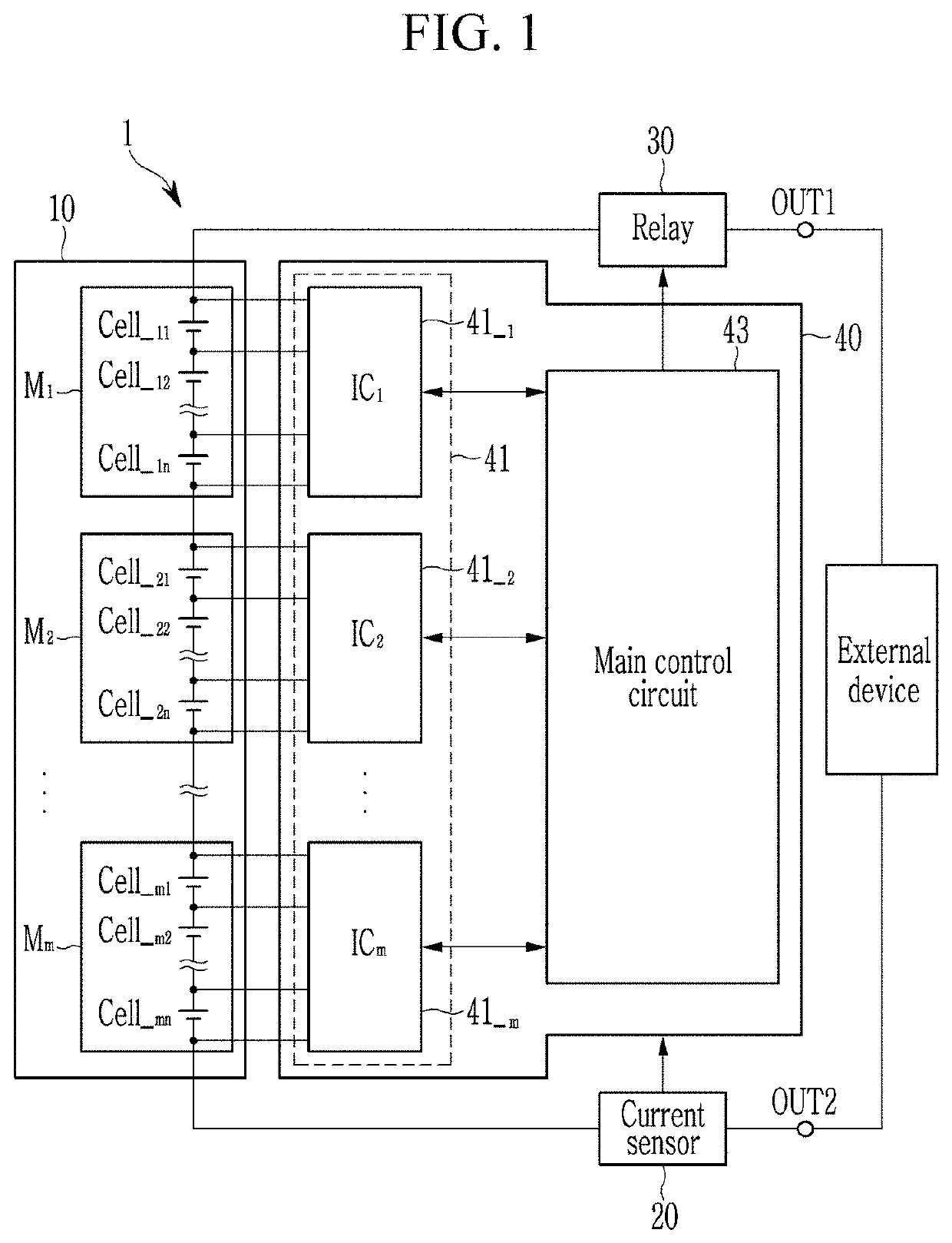
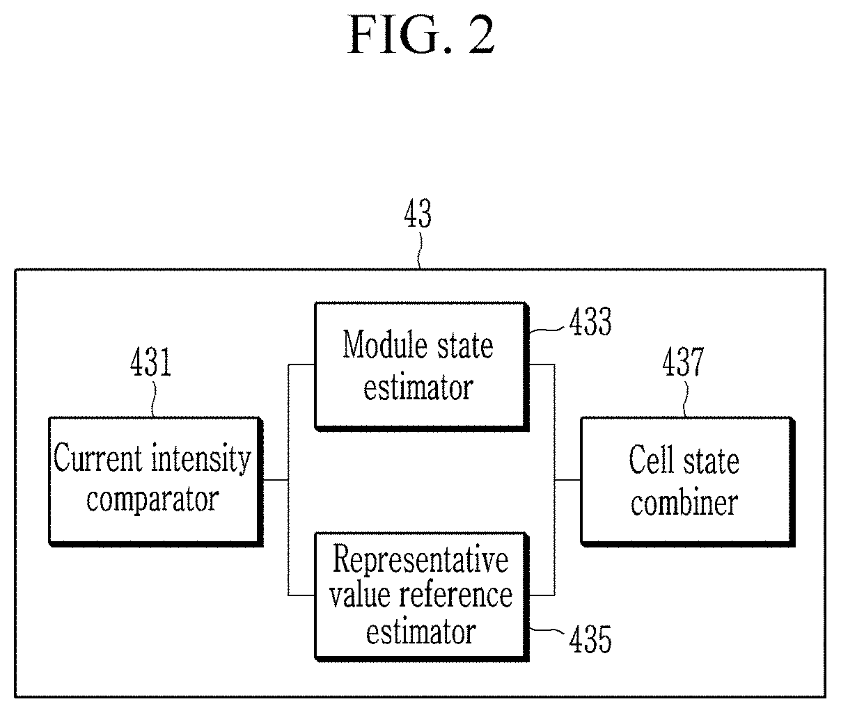
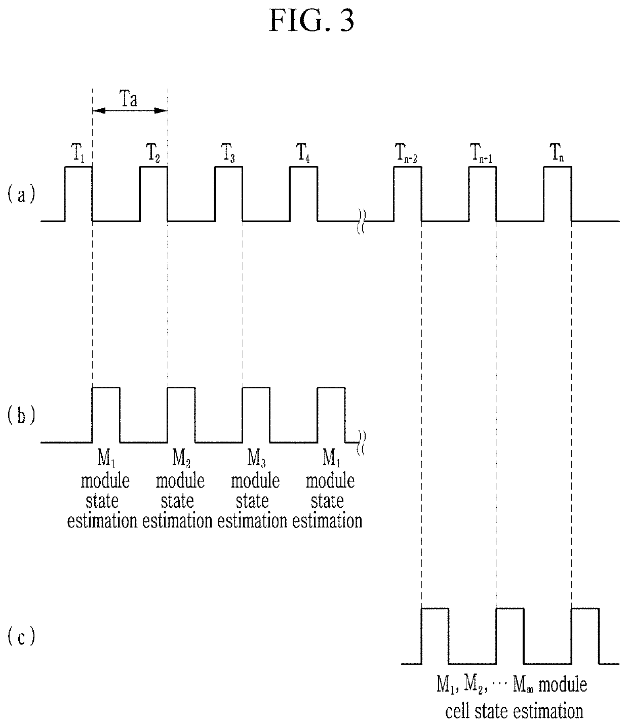
[0028]Hereinafter, embodiments disclosed in the present specification will be described in detail with reference to the accompanying drawings. In the present specification, the same or similar components will be denoted by the same or similar reference numerals, and an overlapped description thereof will be omitted. The terms “module” and “unit” for components used in the following description are used only in order to make the specification easier, and hence, these terms do not have meanings or roles that distinguish them from each other by themselves. In describing embodiments of the present specification, when it is determined that a detailed description of the well-known art associated with the present invention may obscure the gist of the present invention, it will be omitted. The accompanying drawings are provided only in order to allow embodiments disclosed in the present specification to be easily understood and are not to be interpreted as limiting the spirit disclosed in t...


PUM

PropertyMeasurementUnit
state of chargeaaaaaaaaaa
threshold currentaaaaaaaaaa
chargeaaaaaaaaaa

Abstract

The present disclosure relates to a method for estimating a state of charge (SOC) of a battery and a battery management system applying the same. A method for estimating a SOC of a battery in a method for estimating a SOC of a battery module assembly including battery modules respectively including a plurality of battery cells includes: receiving a battery current from a current sensor; comparing the battery current and a threshold current, and selecting a method for estimating a first SOC or a method for estimating a second SOC according to a comparison result; estimating a SOC of the cells according to the selected method for estimating a state of charge; and estimating the SOC of the battery module assembly by combining the estimated SOC of the battery cells.

Description

TECHNICAL FIELD[0001]This application claims priority to and the benefit of Korean Patent Application No. 10-2019-0137548 filed in the Korean Intellectual Property Office on Oct. 31, 2019, the entire contents of which are incorporated herein by reference.[0002]The present invention relates to a method for estimating a state of charge of a battery and a battery management system applying the same.BACKGROUND ART[0003]In recent years, electric vehicles such as a hybrid electric vehicle (HEV) or a pure water electric vehicle (PEV) have gained high attention. The electric vehicle includes a battery for driving an electric motor and driving the vehicle. Further, the electric vehicle includes a regenerative brake system, and braking power may be converted into useful electrical energy for charging the battery through the regenerative brake system. Therefore, the battery included in the electric vehicle may frequently cause transition of a state of charge and a state of discharge.[0004]On t...

Claims


Application Information

Patent Timeline
Patent Type & Authority Applications(United States)
IPC IPC(8): G01R31/3842G01R31/36H01M10/42H01M10/44
CPCG01R31/3842G01R31/3648H01M2010/4271H01M10/441H01M10/425H01M10/4207H01M10/42H01M10/44G01R31/396B60L58/21B60L58/14B60L2240/547B60L2240/549G01R31/3835G01R31/367H02J7/0018H02J7/0048H02J2310/48Y02E60/10G01R31/382G01R19/16542
Inventor SUNG, YONG CHUL
Owner LG ENERGY SOLUTION LTD
Why Eureka
Eureka Blog
Learn More